Probus DP V1 Agile 1706/2010
Baud Rate Setting / Line Length
8 Baud Rate Setting / Line Length
The baud rate is not set explicitly. The Profibus component supports the Auto_Baud
independently determines the baud rate set on the bus.
The maximum line length recommended by the PNO correlates to the baud rate.
100
9 Setting the Station Address
391 Profibus Node-ID
A maximum of 125 slave frequency inverters can be operated on the Profibus-DP. Each frequency inverter
is assigned a node ID for its unambiguous ide
ntification; this ID may only exist once in the system. The
setting of the node ID is carried out via Parameter Profibus Node-ID 391.
391 = -1 means Profibus function switched off.
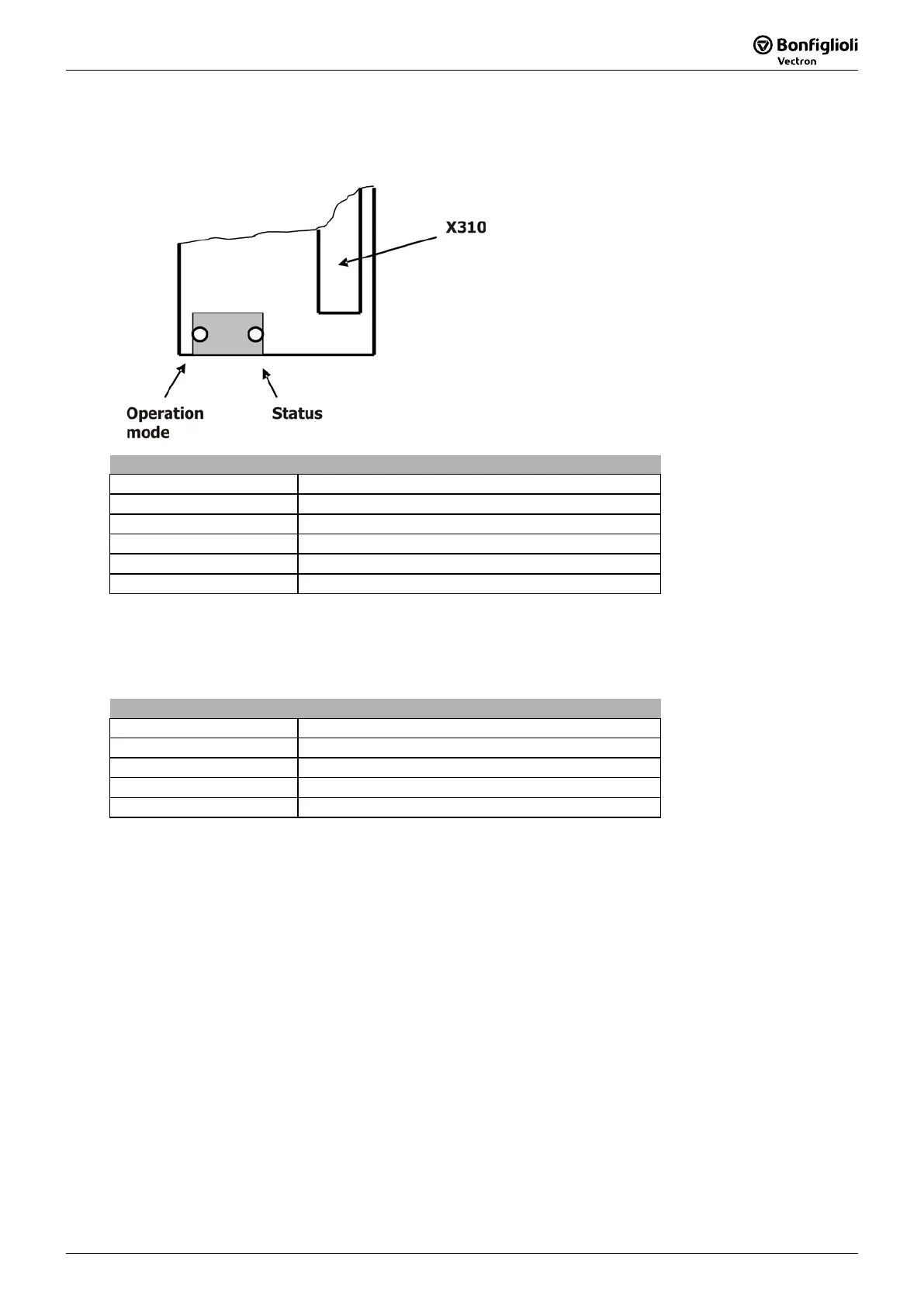
LED Indicators
10 LED Indicators
The communication module has two bicolor LEDs which display the module status and the (Profibus)
operation mode.
Operation Mode
State Indication
Off not online/no power
Green online, data exchange
Flashing Green online clear
Flashing Red (1 flash) parameterization error
Flashing Red (2 flashes) configuration error (*)
* Configuration Error
The configuration error indicates an incorrect configuration of the data exchange object.
See Chapter 13.1"Configuration Process on the DP Master".
Status
State Indication
Off not initialized/no power
Green initialized
Flashing Green initialized, diagnostic event present (*)
Red exception error (**)
* Diagnostic Event
When the inverter enters the error state a diagnostic event is sent from the inverter controller to the
CM-PDPV1. The CM-PDPV1 then sends
a diagnostic message to the Profibus master. The Profibus
master device is then able to display the inverter error. The LED stops flashing after the
acknowledgement of the inverter error.
Note: Diagnostic events are handled by a S7-CPU with OB82/OB86. I
loaded the CPU enters the STOP state in the case of a diagnostic event.
** Exception Error
An exception error indicates a fatal error on the CM-PDPV1 or communication loss between CM-
and inverter controller. Check the inverter error message with the Operator Panel or VPlus.

 Loading...


