Probus DP V1 Agile 5706/2010
281
= C: 6 480 I: 0300 V: -005500 000F 2000 0000 0000 0000 0000
Meaning
6 Request identification = 6 (Read parameter value Array)
480 Parameter number = 480 (Fixed frequency 1)
Parameter value = -5500 = -55.00 Hz (0xFFFEA84 hexadecimal)
Release command (transition 4)
2000 Set point = 0x2000 = 50% of the reference value
0000 not used
284
= C: 5 480 I: 03 00 V: -005500 06A7 2000 1147 0CCC 0800 0000
Reply identification = 5 (Transmit parameter value long Array)
480 Parameter number = 480 (Fixed frequency 1)
Parameter value = -5500 = -55.00 Hz (0xFFFEA84 hexadecimal)
State = 0x27 "Operation enabled“ (Bit 0 ... 6),
Warning 2 present (Bit 15 = 1 threat of fault switch-off),
reference value reached (Bit 10 = 1),
remote operation (Bit 9 = 1),
Warning present (Bit 7 = 1)
Actual value = 0x2000 = 50% of the reference value
Abs. current = 0x1147 = 27% of the rated motor current
Active current = 0x0CCC = 20% of the rated motor current
0800 Warning, Warning motor temperature available
0000 Fault, no fault pending
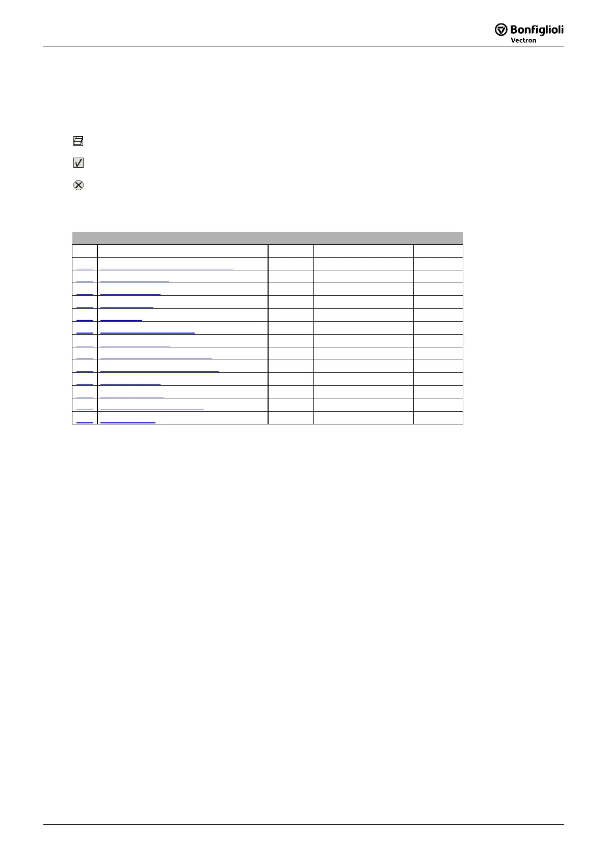
Parameter List
17 Parameter List
The parameter list is structured according to the menu branches of the Operator P
clarity, the parameters have been marked with pictograms:
The parameter is available in the four data sets
The parameter value is set by the SET-UP routine
This parameter cannot be written when the frequency inverter is in operation
17.1 Actual Values
Actual Values of the Frequency Inverter
No. Description Units Display Range Chapter
228 Internal Reference Frequency Hz -1000,00 ... 1000,00 16.4.5
249 Active Data Set - 1 ... 4 16.4.1
250 Digital Inputs - 0 ... 255 16.4.4
260 Actual Error - 0 ... 0xFFFF 18.2
270 Warnings - 0 ... 0xFFFF 18.1
274 Application Warnings - 0 ... 0xFFFF 18.2
281 DP-Master OUT - String 16.5
282 Reference bus frequency Hz -1000,00 ... 1000,00 16.4.5
283 Reference ramp frequency Hz -1000,00 ... 1000,00 16.4.5
284 DP-Master IN - String 16.5
365 Status Control - 0 … 7 11
366 Status Fieldbus Module - 1 … 15 11
411 Status Word - 0 ... 0xFFFF 16.4.1
Note:
The Parameters
281 and
284
can only be displayed via
the VPlus PC-Software.
The Parameters
270,
270 and
274 are
only accessible via the communication channel of objects PPO1, PPO2 and DP-V1. They
cannot be accessed via the VPlus PC-Software or the Operator Panel.

 Loading...


