Probus DP V1 Agile 5306/2010
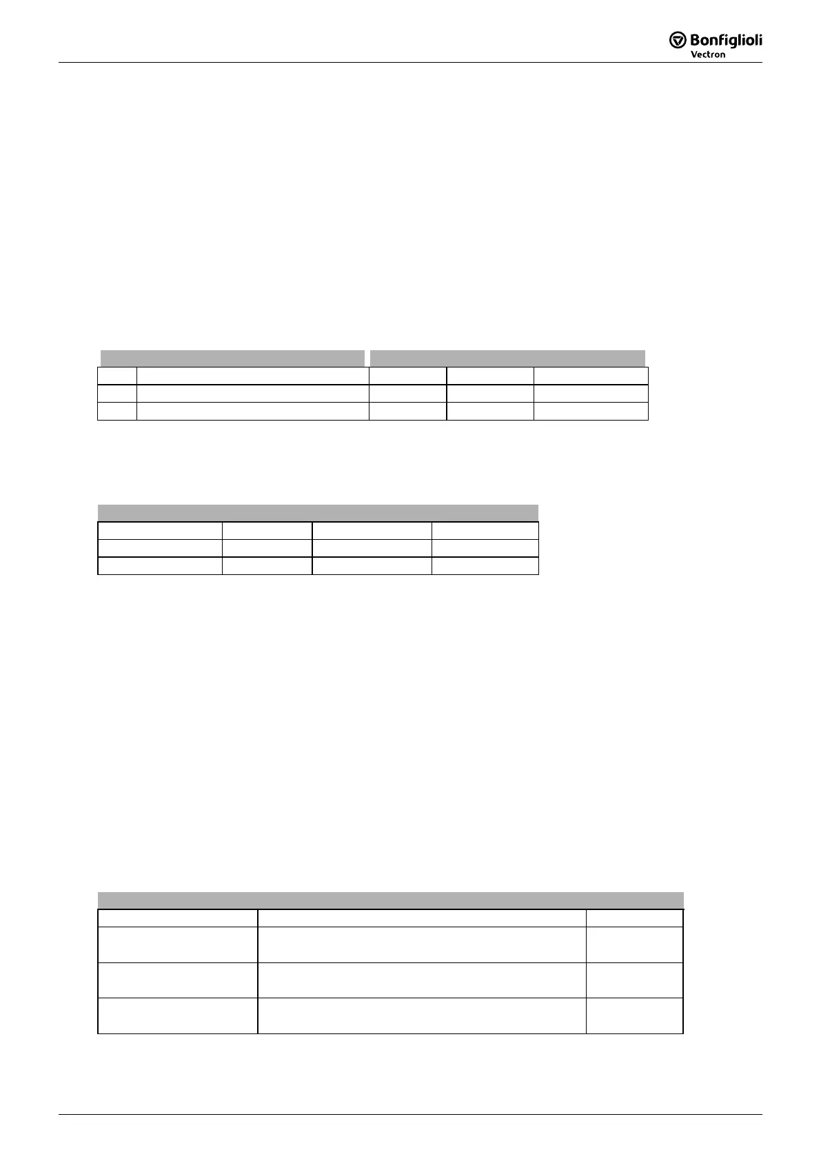
State HEX (*) Bit 6 Bit 5 Bit 3 Bit 2 Bit 1 Bit 0
Switch On 0x23 0 1 0 0 1 1
Operation enabled 0x27 0 1 0 1 1 1
(*) without considering bits 7 to bit 15
The occurrence of a fault leads to a switch-over to the "Fault" state.
A fault can only be acknowledged 15 seconds after its occurrence, as a blocking time is
active internally.
Bit 7 "Warning" can be set at any time. It indicates a device-
internal warning message. The
evaluation of the present warning is carried out by reading out the warning status with parameter
Warnings
is set if the operation mode control via remote contacts (
the hardware release is available. Only then can the frequency inverter be
controlled via the control word.
Bit 10 "Reference value reached" is set whenever the specified reference value has be
en reached.
In the special case of power failure regulation, the bit is also set if the power failure regulation has
reached the frequency 0 Hz (see operating instructions). For "Reference value reached“ there is a
hysteresis (tolerance range), which can be set via parameter Reference Value Reached: Hysteresis
549 (see operating instructions).
Bit 11
"Limit value active" indicates that an internal limit is active. This can, for example, be the
present current limit, the torque limit or the over-voltage l
imit. All the functions lead to the reference
value being quit or not reached.
Bit 15 "Warning 2" indicates a warning which leads to a fault switch-off of the frequency inverter
within a short period of time. This bit is set if there is a warning for mo
sink/inside temperature, Ixt monitoring or mains phase failure.
With the use of remote contacts the signal sources* are taken over from the
Word 410. Signals at the hardware contacts (terminals) are not evaluated by t
standard operation modes (e.g. 71 for S2IND).
For the evaluation of terminal signals special operation modes are avail
denoted with the additional term “(Hardware)” and numbered from 526 to 546.
Exception: The controller release via the hardware contacts STOA (termi
STOB (terminal X210B.2) must be set and Bit 0 “Inverter Release” of the Control Word
must be set.
It is not possible to release the controller only via software.
* Signal sources are:
IN1D ... IN5D,
MFI1D, MFI2D
Handling of the Objects
16.4.5 PZD2, Reference Value / Actual Value
In the PZD2, the master gives its reference value to the frequency inverter in the out
information back on its actual value in the input data set.
The use of the reference/actual value ch
annel depends on the configuration setting (control system). The
actual value is generated from one of the sources according to the control system.
390 Profibus Reference
The reference value and actual value are related to the Parameter
375 OR
the Parameter
Profibus Reference
390.
The distinction is made via the setting of parameter
390. If
390
0, Rated frequency 375 is the reference variable. If Profibus Reference 390 ≠ 0, Profibus Reference
is used as the reference variable. Both parameters are capable of data set change-over.
Parameter Setting
No. Description Min. Max. Factory Setting
375 Rated Frequency 10,00 Hz 1000,00 Hz 50,00 Hz
390 Profibus Reference 0,00 Hz 999,99 Hz 0,00 Hz
Reference and actual values are transmitted in a standardized form. The standardiza
by the variables being related to the reference value (Rated frequency 375 OR Profibus reference
390).
Standardization
Reference Value Binary Decimal Hexadecimal
+ 100% + 2
16384 0x4000
- 100% - 2
49152 0xC000
The possible range = ±200 % = +32768 to -32768 = 0x7FFF to 0x8000
Example:
The setting of parameter
390 is the reference value 60.00 Hz.
required reference frequency is 30.00
Hz. This means 50% of the reference value, thus
the set point 8192 (0x2000) has to be transmitted.
With the reference value
390
a machine can also be operated in the field
weakening area above its reference frequency.
Example:
The parameter
375 is set to a frequency of 50.00
parameter
390 to 100.00 Hz the value range of ± 200 Hz is possible.
The reference value for the frequency inverter from PZD2 is provided by the Fieldbus
Value.
In the Reference Frequency Channel, setting "20 – Fi
eldbus Reference Value" can be selected via
Reference Frequency Value Source 1
475 or
Reference Frequency Value Source
492.
Actual Values
Parameter Content Format
Internal reference
frequency
228
Sum of
Reference Frequency Value Source 1
475
and
Reference Frequency Value Source 2
492.
xxx,xx Hz
282
Fieldbus reference value from Profibus. xxx,xx Hz
283
Actual Ramp Reference Frequency. xxx,xx Hz

 Loading...


