Probus DP V1 Agile 06/201052
Handling of the Objects
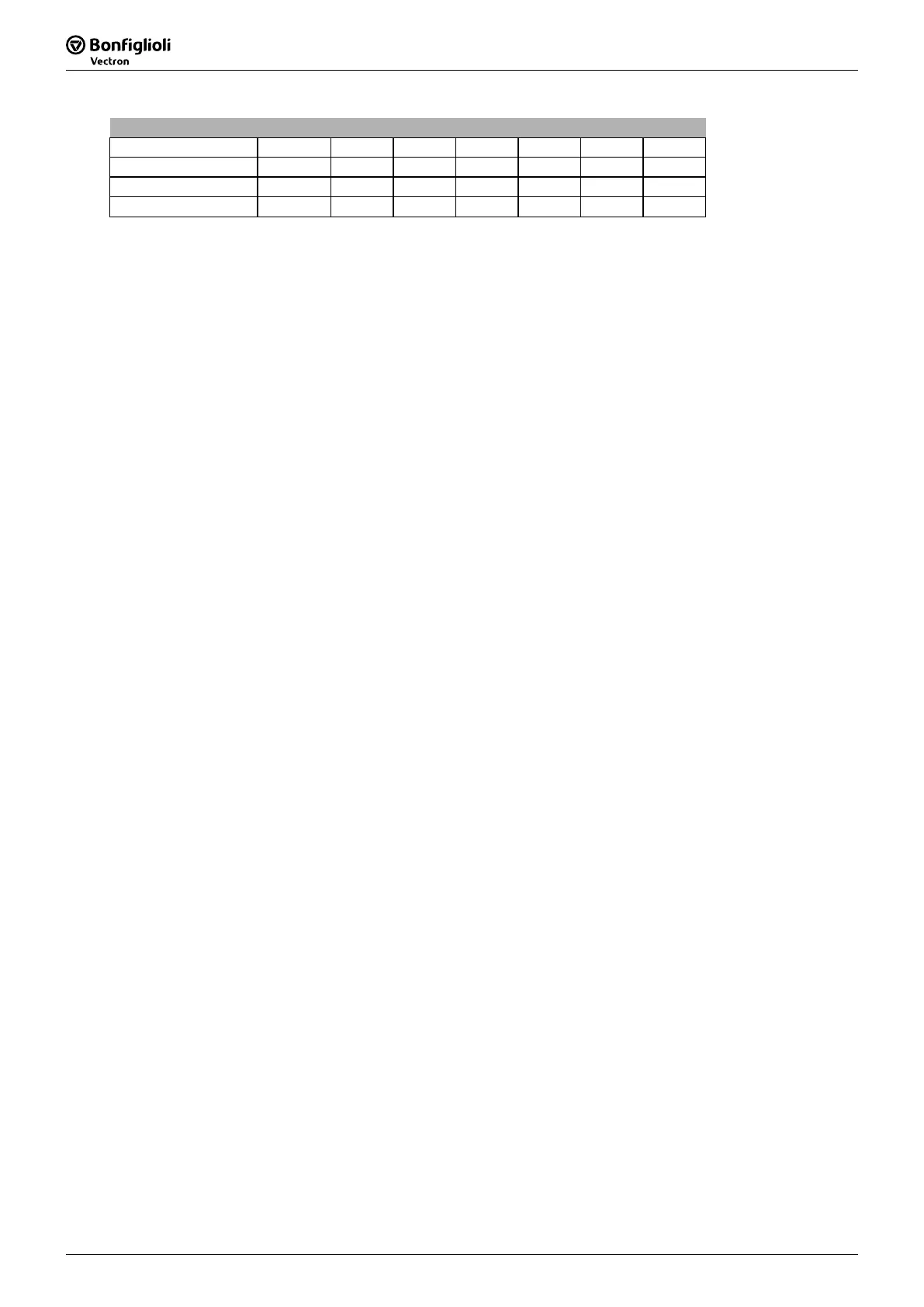
Status Word
State HEX (*) Bit 6 Bit 5 Bit 3 Bit 2 Bit 1 Bit 0
Switch On 0x23 0 1 0 0 1 1
Operation enabled 0x27 0 1 0 1 1 1
Fault 0x08 0 x 1 0 0 0
(*) without considering bits 7 to bit 15
Note: The occurrence of a fault leads to a switch-over to the "Fault" state.
A fault can only be acknowledged 15 seconds after its occurrence, as a blocking time is
active internally.
Bit 7 "Warning" can be set at any time. It indicates a device-
internal warning message. The
evaluation of the present warning is carried out by reading out the warning status with parameter
Warnings
270.
Bit 9 "Remote" is set if the operation mode control via remote contacts (
412
has been set and
the hardware release is available. Only then can the frequency inverter be
controlled via the control word.
Bit 10 "Reference value reached" is set whenever the specified reference value has be
en reached.
In the special case of power failure regulation, the bit is also set if the power failure regulation has
reached the frequency 0 Hz (see operating instructions). For "Reference value reached“ there is a
hysteresis (tolerance range), which can be set via parameter Reference Value Reached: Hysteresis
549 (see operating instructions).
Bit 11 "Limit value active"
indicates that an internal limit is active. This can, for example, be the
present current limit, the torque limit or the over-voltage l
imit. All the functions lead to the reference
value being quit or not reached.
Bit 15 "Warning 2" indicates a warning which leads to a fault switch-
off of the frequency inverter
within a short period of time. This bit is set if there is a warning for mo
sink/inside temperature, Ixt monitoring or mains phase failure.
Note:
With the use of remote contacts the signal sources* are taken over from the
Word 410. Signals at the hardware contacts (terminals) are not evaluated by t
standard operation modes (e.g. 71 for S2IND).
For the evaluation of terminal signals special operation modes are avail
denoted with the additional term “(Hardware)” and numbered from 526 to 546.
Exception: The controller release via the hardware contacts STOA (termi
STOB (terminal X210B.2) must be set and Bit 0 “Inverter Release” of the Control Word
must be set.
It is not possible to release the controller only via software.
* Signal sources are:
IN1D ... IN5D,
MFI1D, MFI2D

 Loading...


