Probus DP V1 Agile 5906/2010
Parameter List
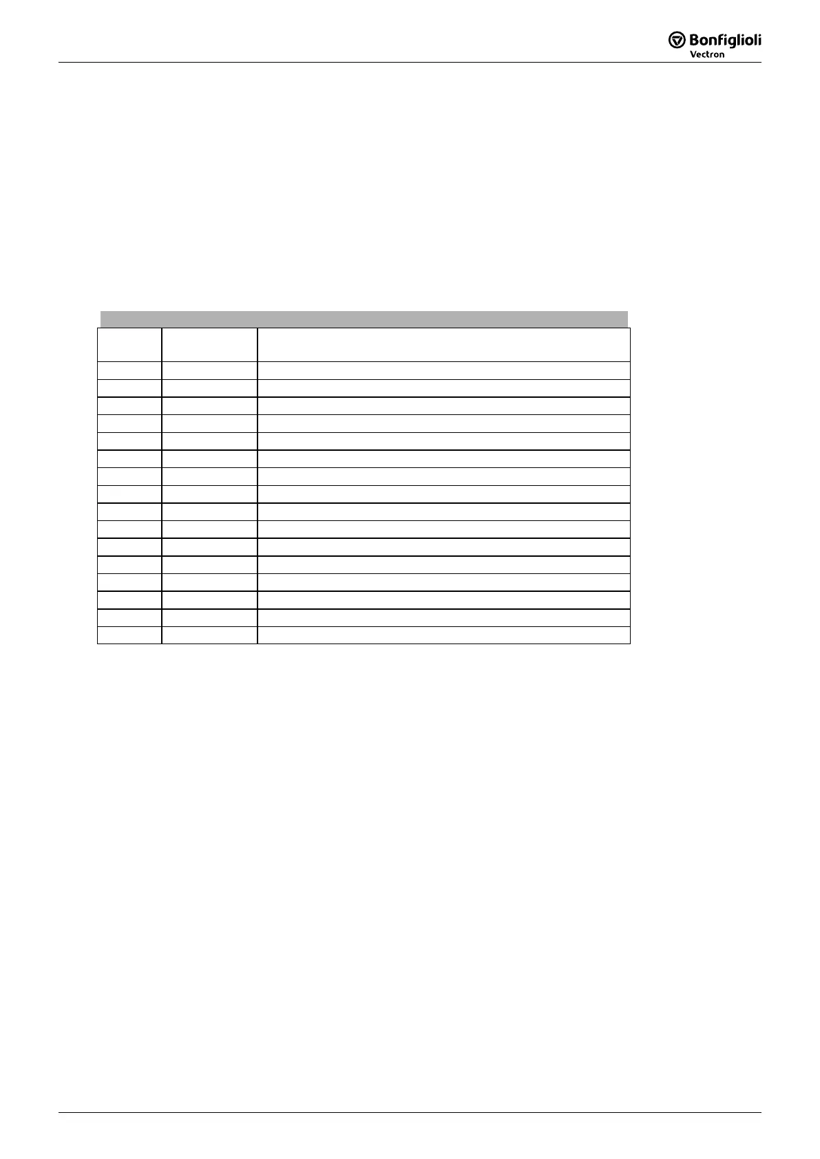
17.2 Parameters
Profibus
391 Profibus Node-ID - -1 ... 126 9
412 Local/Remote - 0 ... 44 16.4.1
425 Emergency stop anticlockwise Hz/s 0,01 ... 9999,99 16.4.3.1
549 Reference Value Reached:Hysteresis % 0,01 ... 20,00 16.4.2
638 Holding Time Stop Function s 0,0 ... 200,0 16.4.3.1
1300 In-PZD 3 Boolean - 16.3.3
.
. all In-PZD Parameter
.
1371 In-F-PDP-word 2 - Selection 16.4
1373 In-F-intern-long 2 - Selection 16.4
is only accessible via the communi
channel of objects PPO1 and PPO2. It cannot be accessed via the Vplus PC-
Software or the Operator Panel.
Annex
18 Annex
18.1 Warning Messages
The various control functions and methods and the hardware of the frequency inverter contain
functions that continuously monitor the application. In addition to the messages documented in the
manual, the following warning messages are activated by the Profibus-
CM-PDPV1.
The warning messages are given via parameter
Warnings 270, bit-coded according to the following
scheme.
Parameter
Warnings 269 shows the warnings in clear text on the operator panel
software tool VPlus.
Use Parameter
270 to access the warning codes via Profibus.
Warning Messages
Bit-No. Warning
Code
Description
0 0x0001 Warning Ixt
1 0x0002 Warning Short Term - Ixt
2 0x0004 Warning Long Term - Ixt
3 0x0008 Warning Heat Sink Temperature Tk
4 0x0010 Warning Inside Temperature
5 0x0020 Warning Limit
6 0x0040 Warning Init
7 0x0080 Warning Motor Temperature
8 0x0100 Warning Mains Failure
9 0x0200 Warning Motor Protective Switch
10 0x0400 Warning Fmax
11 0x0800 Warning Analog Input MFI1A
12 0x1000 Warning Analog Input MFI2A
13 0x2000 Warning Systembus
14 0x4000 Warning Udc
15 0x8000 Warning Application
Note: The meaning of the individual warnings are described in detail in the operating
instructions.

 Loading...


