Probus DP V1 Agile 2506/2010
Available Objects / Scanning Times
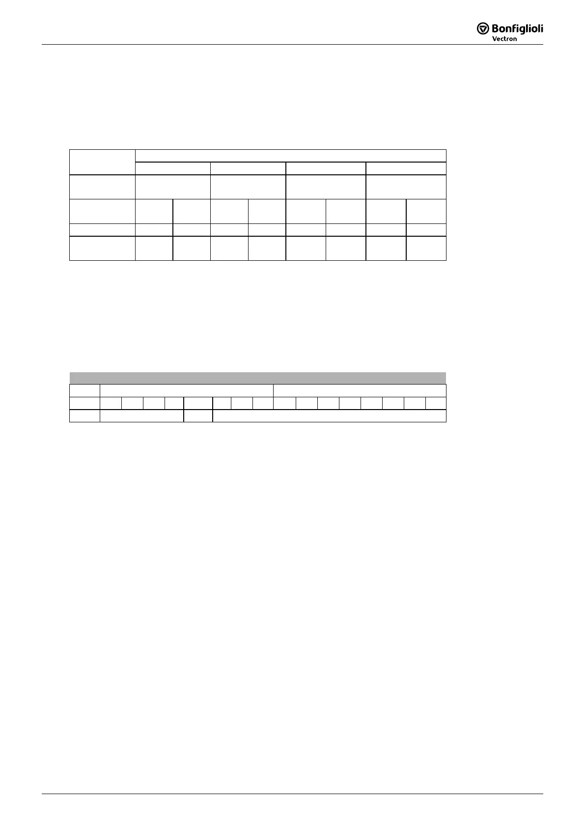
Scan time defines the data update cycle between the Profibus module CM-
controller which processes the Profibus data. This scan time is independent of the bus rotation time.
Regardless of the transmission speed on the Profibus, the scanning time of the in
of the configured objects and the resultant object length (number of bytes).
No. of configured
36 18 4
The scan time is dependent on the number of configured objects.
Handling of the Objects
16 Handling of the Objects
This chapter describes the handling of the communication channels like i.e. Process data channel and
Parameter data channel.
16.1 Parameter Access via Communication Channel PKW
The communication channel (PKW area) has the following structure:
Designation
PKW Area
PKE PKE
Content
Parameter
identification
Content
Parameter
identification
Content
High
Byte
High
Byte
High
Byte
High
Byte
Byte No. 0 Byte
No.
0 Byte
No.
0 Byte
No.
0 Byte
No.
The data is transmitted in the Motorola format
as, for example, supported by the S7 PLC from
Siemens. Thus, the high byte is on the lower byte of the telegram and the low byte on the higher
byte.
Note: The data set is always on the high byte of "Index“ (data set/Byte No. 2).
If the Systembus function is available (EM-
module with Systembus) a Systembus address
is set on the low byte of “Index” (SB/Byte No. 3). With the help of this parameter the
access to a Systembus subscriber is possible. For details see the Systembus manual.
Structure of the Parameter Identification (PKE):
PKE High-Byte Low-Byte
Bit 15 14 13 12 11 10 9 8 7 6 5 4 3 2 1 0
AK SPM PNU
AK: Request or reply identification (value range 0 ..15)
SPM: Toggle bit for spontaneous result processing
PNU: Parameter number (value range 1 to 1599)
The request and reply identifications are stored in the AK area. If no parameter processing is to be
carried out, the “no request” type of function is to be set.
With bit 11
(SPM), the readiness for spontaneous report processing can be switched on and off (0 =
OFF, 1 = ON, in the present application, the spontane
ous report processing is not supported, so SPM
is always 0).
The PNU area transmits the number of the parameter to be processed.
Parameter values (= data) of the type Integer/Unsigned Integer (16 Bit) and Long (32 Bit) can be
written and read. The data type is specified in the request identification. In data set change-
capable parameters (array), the required data set is stated in the Index Byte (Byte 2).
Note: An Excel file, which is available on request, exists for the necessary infor
parameters with regards to the data type and data set change-over capability.
Note: To obtain access to the PKW object on a S7 PLC the functions SFC14/15 must be used.

 Loading...


