Probus DP V1 Agile 4306/2010
The Status Word reflects the operation state.
(*) without considering bits 7 to bit 15
The occurrence of a fault leads to a switch-over to the "Fault" state.
can be set at any time. It indicates a device-
internal warning message. The
evaluation of the present warning is carried out by reading out the warning status with Parameter
Warnings
Bit 9 "Remote" is always = 0.
Bit 10 "Reference value reached" is set whenever the specified refer
ence value has been reached.
In the special case of power failure regulation, the bit is also set if the power failure regulation has
reached the frequency 0 H
z (see operating instructions). For "Reference value reached“ there is a
hysteresis (tolerance range), which can be set via parameter Reference Value Reached: Hysteresis
549 (see operating instructions).
Bit 11
"Limit value reached" indicates that an internal limit is active. This can, for example, be the
present current limit, the torque limit or the over-
voltage limit. All the functions lead to the reference
value being quit or not reached.
Bit 15 "Warning 2" indicates a warning which leads to a fault switch-off of the frequency inverter
within a short period of time. This bit is set if there is a warn
ing for motor temperature, heat
sink/inside temperature, Ixt monitoring or mains phase failure.
Handling of the Objects
16.4.3 Control via State Machine
In the operation mode control via state machine (
412 = 1), the fre
controlled via the control word in PZD1. The diagram shows the possible states.
State transition 4 to state “Operation enabled” is only possible if the controller release via STOA a
STOB and a digital input for Start Clockwise or Start Anticlockwise are set.
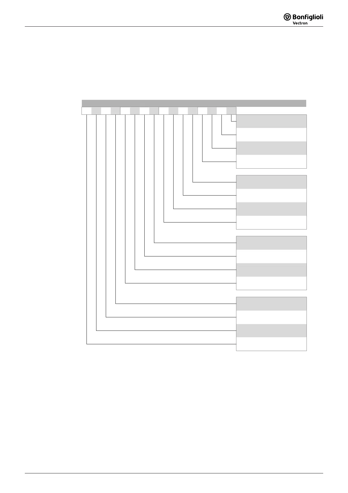
Control Word
15
14 13 12 11 10 9 8 7 6 5 4 3 2 1 0 Bit
0
Switch On
1
Enable Voltage
2
Quick Stop
3
Enable Operation
4
no function
5
no function
6
no function
7
Reset Fault
8
no function
9
no function
10
no function
11
no function
12
no function
13
no function
14
no function
15
no function

 Loading...


