Probus DP V1 Agile 3306/2010
Handling of the Objects
16.2.1 Operation Mode "Standard"
A parameter is accessed by its parameter number and data set number. The valid range for parameter
number is 0 … 1599, the range of data set number is 0 … 9.
For the handling of data set selection see chapter 16.1.4 "
Parameters, Data Set Selection
and Cyclic Writing".
The standard mode uses the direct setting of Profibus node ID,
slot
and
index
. With the setting of the
two 8 bit objects
slot
and
index
the selection of parameter number and data set number for
read/write is done. The number of bytes to be transferred (read/write) depends on the parameter's
data type. In the case of a write cycle and an invalid number of bytes the CM-PDPV1 protoc
Calculation of slot and index:
Calculate an "application data index" ADI as a 16 bit unsigned integer with
ADI = (Parameter number + 1) + (2000 * (Data Set number + 1))
Calculate the value of
slot
and
index
with
slot = (ADI – 1) / 255
index = (ADI – 1) modulo 255
Parameter number = 480
Data Set number = 3
ADI = (480 + 1) + (2000 * (3 + 1)) = 8481
slot = (8481 - 1) / 255 = 33
index = (8481 - 1) modulo 255 = 65
The parameter data structure is explained above.
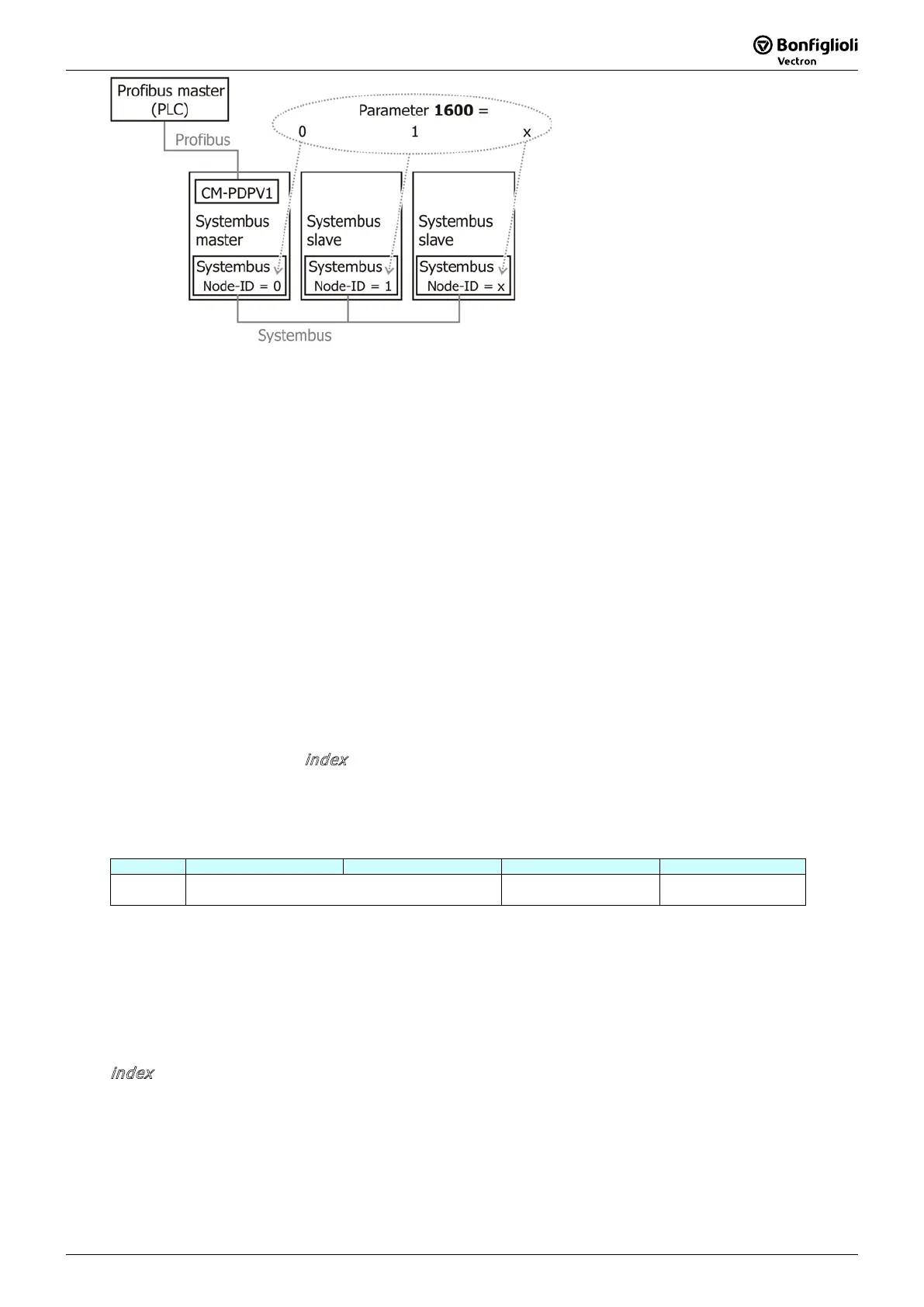
Access to Systembus:
The Standard Mode also offers a special functionality to obtain access to additional inverters via the
Systembus. For example, there exists one inverter with CM-
PDPV1 and several additional inverters
coupled to the first one via the Systembus.
This function can be implemented with CM-PDPV1 via the virtual parameter 1600.
After power on/reset this virtual parameter 1600 is set to zero. With 1600
accesses by V1 channel are allocated to the inverter with CM-PDPV1 itself.
Handling of the Objects
To obtain access to parameters of inverters via the Systembus, parameter 1600
desired Systembus node ID.
The data type of parameter 1600 is unsigned integer with a valid data range = 0 … 63.
Parameter 1600 can be read and written.
16.2.2 Operation Mode "S7 Compatible"
A parameter is accessed by its parameter number and data set number. The valid range for parameter
number is 0 … 1599, the range of data set number is 0 … 9.
Note: For the handling of data set selection see chapter 16.1.4 "
Parameters, Data Set Selection
and Cyclic Writing".
The S7-compatible Mode only allows the setting of the object
index
. There are two steps necessary
for reading/writing one parameter. The number of bytes to be trans
ferred (read/write) depends on
the parameter's data type. In the case of a write cycle and an invalid number of bytes the CM-P
protocol reacts with an error message.
Step 1:
In the first step the desired parameter number, data set number and Systembus node ID are written.
This message is sent with
index
set to 1
. The object to be sent has 4 bytes with the following
structure:
Data Structure for Index = 1:
Byte 0 1 2 3
Content Parameter Number
High Byte Low Byte
Data Set Number Systembus
Address
Parameter number = 0 …. 1599
Data Set = 0 …. 9
Systembus Address = 0 …. 63
Step 2:
The desired parameter data can now be read or written by sending a read or write request with
i
ndex
set to 2.
The parameter data structure is explained above.

 Loading...


