EasyManua.ls Logo

BONFIGLIOLI Vectron Agile Series User Manual

BONFIGLIOLI Vectron Agile Series
64 pages
To Next Page IconTo Next Page
To Previous Page IconTo Previous Page
Page #39 background image
Probus DP V1 Agile 3906/2010
Handling of the Objects
Note:
The displayed "PDP active current" depends on the control system. In field-
orientation,
the torque-
forming current is displayed, in applications with a v/f characteristic control,
the active current, which is also a measure for the torque.
The “PDP absolute current” (r.m.s. current) is always positive. Active current and torque-
forming current have a sign prefixed.
Positive currents = motor
Negative currents = generator operation.
Current Scaling
Standardization
Reference value Binary Decimal Hexadecimal
+ 100% + 2
14
16384 0x4000
The possible range = ±200% = +32768 to -32768 = 0x8000 to 0x7FFF
For the internal scaling, the data set change-over capable parameter
Rated current 371 is used as a
reference.
Parameter
Setting
No.
Description
Min.
Max.
Factory Setting
371 Rated Current 0,01 · I
FUN
10 · I
FUN
I
FUN
Handling of the Objects
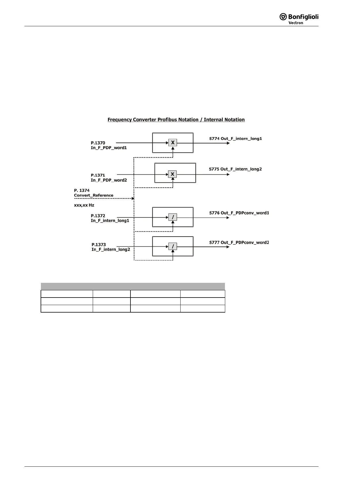
16.4 Frequency Conversion PDP Word to/from Inverter Internal Notation
1370 In-F-PDP-word 1
1371 In-F-PDP-word 2
1372 In-F-intern-long 1
1373 In-F-intern-long 2
1374 In-F-Convert Reference
The function
Convert PDP/intern
converts frequency values in Profibus
notation to frequency values in
device-internal notation and vice versa. See Chapter 16.4.5 "PZD2, Reference Value / Actual Value".
The scaling for In_F_PDP_word1/2 and Out_F_PDPconv_word1/2 is:
Standardization
Reference Value Binary Decimal Hexadecimal
+ 100% + 2
14
16384 0x4000
- 100% - 2
14
49152 0xC000
The possible range = ±200% = +32768 to -32768 = 0x7FFF to 0x8000
This function uses its own reference value
Convert-Reference
1374 for data conver
sion. The benefit
of this function is the usage of the word data type for frequency values, instead of long.
Note: The usage of this function and the usage of In-PZD/Out-
PZD objects is shown in the
sample project documented with:
CM_PDPV1_conf.pdf Cluster with one inverter and CM-PDPV1 and three additional
inverters coupled by Systembus
CM_PDPV1_S7.pdf Functional description
CC_0B2C.zip Complete STEP7 project including samples for In/Out-PZD usage
and parameter access via PKW object and V1 channel
S7-SoftwareOB1.pdf Listing of OB1 from STEP7 project

Table of Contents

Question and Answer IconNeed help?

Do you have a question about the BONFIGLIOLI Vectron Agile Series and is the answer not in the manual?

BONFIGLIOLI Vectron Agile Series Specifications

General IconGeneral
Fieldbus CommunicationCANopen, Modbus RTU
ProtectionOvervoltage; Undervoltage
Control InterfaceDigital Inputs, Analog Inputs
Operating Temperature Range-10°C to +50°C
Cooling MethodLiquid cooling
Enclosure RatingIP20
DimensionsVaries by model
WeightVaries depending on the model
Storage Temperature Range-20°C to 70°C

Summary

General Information on the Documentation

Instruction Manuals

Describes the various manuals available for the Agile device series for different user needs.

General Safety Instructions and Information on Use

General Information

Provides general warnings regarding high voltage, hot surfaces, and the need for qualified personnel.

Purpose of the Frequency Inverters

Explains the intended industrial applications of frequency inverters and compliance with directives.

Transport and Storage

Outlines proper procedures for transporting and storing the frequency inverters to maintain their condition.

Handling and Installation

Covers essential precautions for handling, installation, and electrical installation to prevent damage and ensure safety.

Electrical Installation

Details safety rules and compliance requirements for electrical installation work on the inverters.

Information on Use

Details operational guidelines, restart procedures, and checks before commissioning.

Using external products

Advises on the responsibility for compatibility when using external products with the inverter.

Maintenance and Service

Stresses the importance of authorized personnel for maintenance and service to prevent injury or damage.

Disposal

States that disposal must be carried out according to local and country-specific regulations.

Communication Options

VPlus PC-Software

Explains how to connect a PC via USB adapter to the X21 interface for parameterization and monitoring.

Installation of an optional Communication Module

Assembly

Provides step-by-step instructions for assembling the communication module onto the frequency inverter.

Disassembly

Details the procedure for safely removing the communication module from the frequency inverter.

Connection

Commissioning via the Operator Panel

Menu for setting up the Communication

Guides users on how to configure communication interfaces and parameters using the operator panel menus.

Select the Protocol

Describes how to select the communication protocol (e.g., Profibus) within the setup menu.

Set the Communication Parameters

Explains how to set specific communication parameters like Node Number using the operator panel.

Profibus

Baud Rate Setting / Line Length

Setting the Station Address

LED Indicators

Status Parameters

Error Behavior

Setting PPO Type

Configuration Process on the DP Master

Illustrates the configuration steps using a Siemens STEP7 hardware configurator example.

Commands SYNC / FREEZE

Available Objects / Scanning Times

Handling of the Objects

Parameter Access via Communication Channel PKW

Details the structure and usage of the PKW area for parameter access and identification.

Parameter Access via the DP-V1 Channel

Describes an alternative method for parameter access using the Profibus V1 channel.

Process Data Channel

Describes the handling of Process Data Objects (PZDs) for data exchange.

Frequency Conversion PDP Word to/from Inverter Internal Notation

Explains the function for converting frequency values between Profibus and internal notations.

Actual Value Display of Profibus Data

Explains how Profibus data is displayed in a processed form via PC software.

Parameter List

Actual Values

Lists actual values of frequency inverter parameters, their units, display range, and relevant chapters.

Parameters

Lists various parameters related to Profibus communication, control, and stopping behavior.

Annex

Warning Messages

Details warning codes and their descriptions activated by the Profibus-DP module.

Warning Messages Application

Lists application-specific warning codes and their descriptions.

Error Messages

Explains the structure of error codes and lists common communication errors.

Related product manuals