Probus DP V1 Agile 2306/2010
Commands SYNC / FREEZE
14 Commands SYNC / FREEZE
The Profibus component supports the Profibus commands SYNC/UNSYNC and FREEZE/UNFREEZE. These
commands are used to synchronize a number of slaves.
With the FREEZE command, all the slaves keep
their input data. They are then read out in sequence by the
bus master. As all the slaves keep their inputs simultaneously with the FREEZE command, the bus master is
given a process pattern of all the slaves at a defined time. With the UNFREEZE command, th
cancelled and the slaves update their inputs again.
With the SYNC command, all the slaves retain their current outputs. Subsequently arriving data are not put
through to the outputs, but buffered. The bus master can give new commands to the
slaves and activate
all the slaves simultaneously with the UNSYNC command. They immediately transfer the buffer data to
their outputs with the UNSYNC command.
15 Available Objects / Scanning Times
If a Profibus slave has been recognized, parameterized an
d configured by its master on the bus, there is a
cyclic exchange of data with the Profibus DATA_EXCHANGE
service, in which the output data are
transmitted from the master to the slave and the input data from the slave to the master in one cycle
The repetition rate with which the slaves carry out the exchange of data with the master, the so-
called bus
rotation time, is a function of the transmission rate, the number of subscribers and the size of the objects
transmitted. If there are few subscribers, a hig
h transmission rate and short objects being exchanged, bus
rotation times of 1 to 2 ms are possible.
It is therefore sensible to configure the objects to suit the application. Depending on the application the
focus can be transmission speed, number of objects or a combination of both.
The configured data exchange objects have principally two components, which are either completely, partly
or not at all existent with the differing object configurations. These components are the communication
channel and the process data channel.
The communication channel (PKW object) is used for accessing (write/read) parameters in the
frequency inverter. An exception is formed by the string parameters, to which there is NO access. The
communication proceeds according to a firmly defined hand-
shake process and lasts for a number of
The process data channel (PZD objects) is processed in every cycle. The reference values are accepted
and the actual values forwarded. Therefore a data update takes place with every DATA_EXCHANGE.
Direction of transmission Master Slave (OUT)
Parameter identification value
PZD Process data channel STW = Control word HSW = Main reference value
Outx = user defined
Available Objects / Scanning Times
Direction of transmission Slave
Master (IN)
Communication Channel Process Data Channel
PKW area PZD area
PKE IND PWE PWE PZD 1 PZD 2 PZD x PZD x PZD x PZD x
PWEh PWEl ZSW HIW Inx Inx Inx Inx
PKW Parameter identification value
PZD Process data channel ZSW = State word HIW = Main actual value
Inx = user defined
Consistency area
Communication Channel Process Data Channel
PKW area PZD area
PKE IND PWE PWE PZD 1 PZD 2 PZD x PZD x PZD x PZD x
full length word word word word word word
The consistency area describes the parts of the object which must have consistent contents. The
consistency states are encrypted in
the configuration data of the GSD file and have effects on the
possible access mechanisms on the part of the DP master. In this way, the 8 bytes of the
communication channel in a PLC of type Siemens S7 can only be reached via the special functions
SFC14 (DPRD_DAT) and SFC15 (DPWR_DAT)
. The words of the process data channel are directly
addressable as periphery input/output words (PEW, PAW).
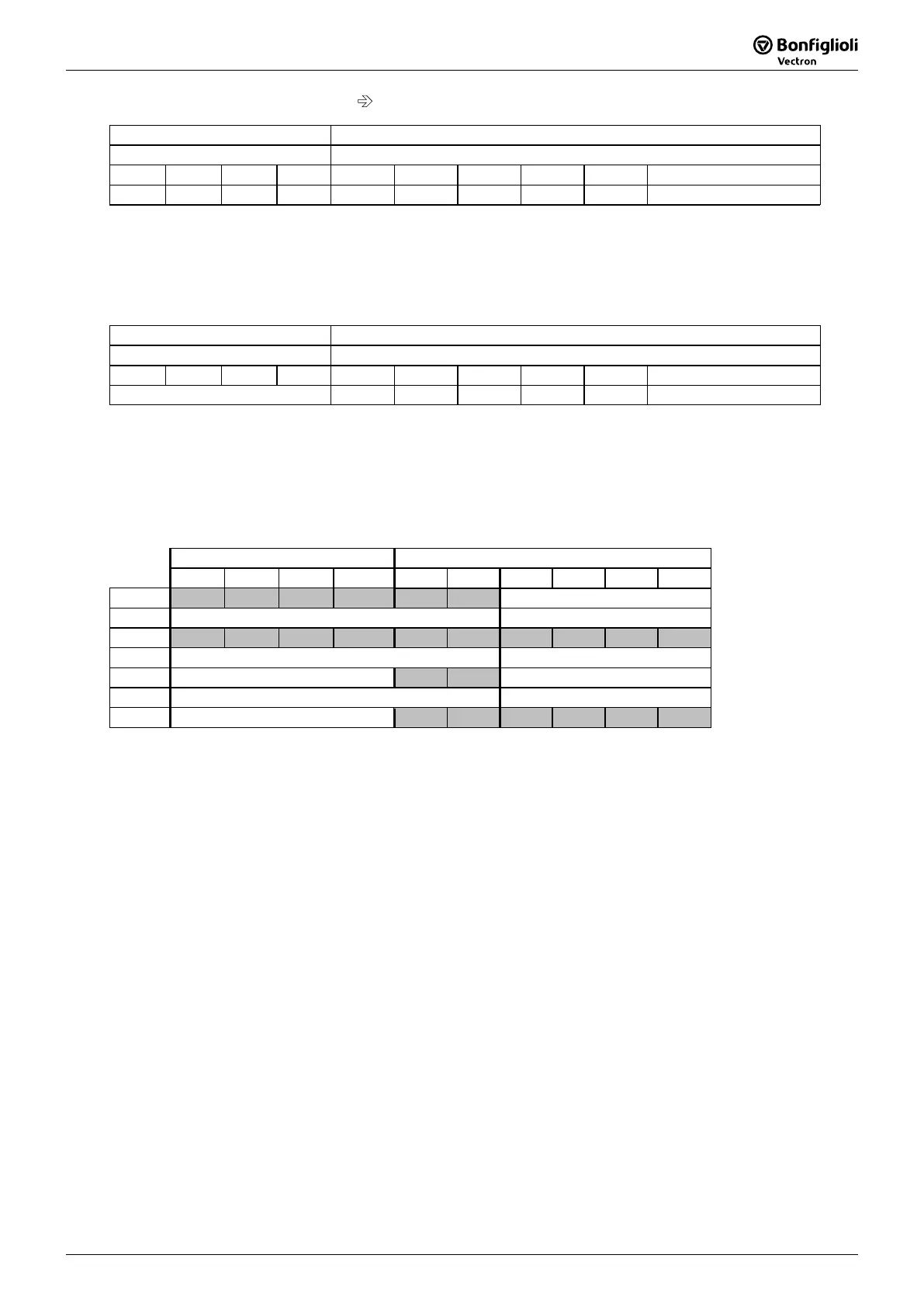
Communication Channel Process Data Channel
PKE IND PWEh PWEl PZD1 PZD2 PZD3 PZD4 PZD5 PZD6
PPO1
PPO2
PPO3
PPO4
PPO1 … PPO4 are predefined configurations. With the help of the PZD- and PKW-
to build your own application specific configuration.
The communication channel is always treated identically. This is valid for the pre
PPO1/PPO2 and custom specific configuration with communication object PKW.
The process data channel objects PZD1/PZD2 are firmly defined and its contents cannot be altered.
The contents of process data channels PZD3 to PZD 18 (maximum, without com
PKW !) is user defined.
Note: In the data transmission, the Motorola format
is presupposed for the position of
Low/High byte first, as is also supported by a PLC of the type Siemens S7. I
f the DP master
supports the Intel format, Low/High byte are to be swapped on the master side before
transmission and after receipt.

 Loading...


