1 689 989 403 2019-03-01| Robert Bosch GmbH
20 | Denoxtronic 1.1 | Devices and componentsen
3. Devices and components
i This section provides an overview of the most im-
portant devices and components that are required
for testing and repairing the AdBlue supply mod-
ules, type Denoxtronic 1.1. Detailed instructions
on use and handling can be found in the separate
ESI[tronic] repair instructions Denoxtronic 1.1.
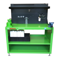
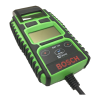
3.1 Test device 0986613880
The test device 0 986 613 880 is intended to be used
together with all Denoxtronic toolsets as a workplace
for testing and repairing AdBlue supply modules.
The test device has all supply connections for the test
medium, test voltage, compressed air and calibration gas.
Fig. 1: Test device 0 986 613 880
i An example is shown in the figure (fig. 1). Informa-
tion on the scope of the delivery and setup can
be found in the original operating instructions
1689989164.
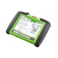
3.2 Adapter module 0 986 610 170
i The adapter module is a part of case 0986610800
(Denoxtronic-Set 1).
In tests of AdBlue delivery modules, the adapter mod-
ule 0 986 610 170 is used as an interface between the
test adapter 0 986 610 172, KTS5XX / 6XX and the dos-
ing and delivery module.
The adapter module and the connecting cables are
used to supply both the test adapter and the delivery
module with voltage (24V). A voltage stabilizer (30V
DC / min. 20A), e.g. Bosch 1 687 022 873, supplies the
adapter module with voltage.
The diagnostic data for the test is available from the
ESI[tronic] component diagnosis. A subscription to the
ESI[tronic] info type "K" is required.
The control unit in the delivery module is diagnosed
by its self-diagnosis system and the internal OBD fault
memory. The diagnosis includes reading/deleting the
OBD fault memory, an actuator test and function tests.
Fig. 2: Adapter module 0 986 610 170
i The test is carried out with the adapter module 0
986 610 173 for the Scania make. The adapter mod-
ule is not included in the scope of delivery and must
be ordered separately.
i The proper way to connect and use the adapter
module is described in the ESI[tronic] test and
repair instructions.
i A defective adapter module must be replaced in its
entirety.

 Loading...