Solution 6000
Installation Manual Comms Programming
9-8
Bosch Security Systems 07/14 BLCC610I
the panel is able to report this signal via an alternative
reporting method such as the GSM cellular network.
If no alternative route exists then the panel will send the
signal and restore when the PSTN line is reconnected.
Alarm L/Fail If On
This option sets the panel to trigger an alarm when the
telco line fails provided that the area is turned All On or
Part On. In a multi-area system this option is global and
will be triggered if only one area in the system is in the
armed state. The alarm will continue to sound until a
valid PIN is entered or the siren timer expires.
Alarm L/Fail If Off
This option sets the panel to trigger an alarm when the
telco line fails provided that the area is turned OFF or
disarmed. In a multi-area system this option is global and
will be triggered if only one area in the system is in the
disarmed state. The alarm will continue to sound until a
valid PIN is entered or the siren timer expires.
Digital Line
If you are having issues reporting or with RAS
connections and the system is connected to a VOIP or
NBN digital line then you should set the Digital Line
option to yes.
This option has been added in version 2.15.
Low Voltage
If the PSTN line voltage at the panel when the dialler is
on line is below 6 volts DC then you should set the Low
Voltage option to yes.
This option has been added in version 2.15.
Display On Line
This option allows the keypad to display Phone In Use
when the telephone line has been looped by the control
panel for either incoming or outgoing calls. If this option
is disabled, no indication is provided on the keypad.
The dialler status indicator LED located on the main
panel will always show the status of the dialler. See
Section 3 - Wiring Diagrams for more information.
Comms > Properties >
Country
MENU 5-2-3
(*** System Wide Parameter ***)
0 1
Ln1 AUSTRALIA Ln9 CZECH REPUBLIC
Ln2 NEW ZEALAND Ln10 POLAND
Ln3 ITALY Ln11 TURKEY
Ln4 GREECE Ln12 CHINA
Ln5 CYPRUS Ln13 HONG KONG
Ln6 SPAIN Ln14 MALAYSIA
Ln7 PORTUGAL Ln15 BRAZIL
Ln8 HUNGARY
This menu automatically sets the dialling parameters
including dial and busy tones etc. for the country the
panel is working in.
1) Press [MENU] + [5] + [2] + [3]. The keypad will
display the currently selected country. The default
country is Australia.
2) Use the up and down arrow keys to select the
appropriate country then Press [OK].
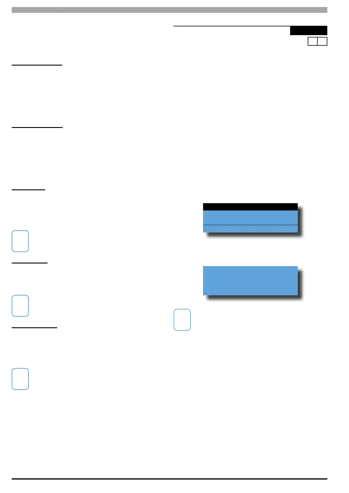
Ln1 AUSTRALIA
Ln2 NEW ZEALAND
Ln3 ITALY
Press OK or MENU
3) Press [OK] to confirm and save and exit or press
[MENU] to exit without saving.
WARNING: Press OK to set
dialler to
AUSTRALIA
For correct dialler operation, you must make sure
that the correct country selection is made for your
location. If your country is not listed here please
contact your distibutor.