1-11
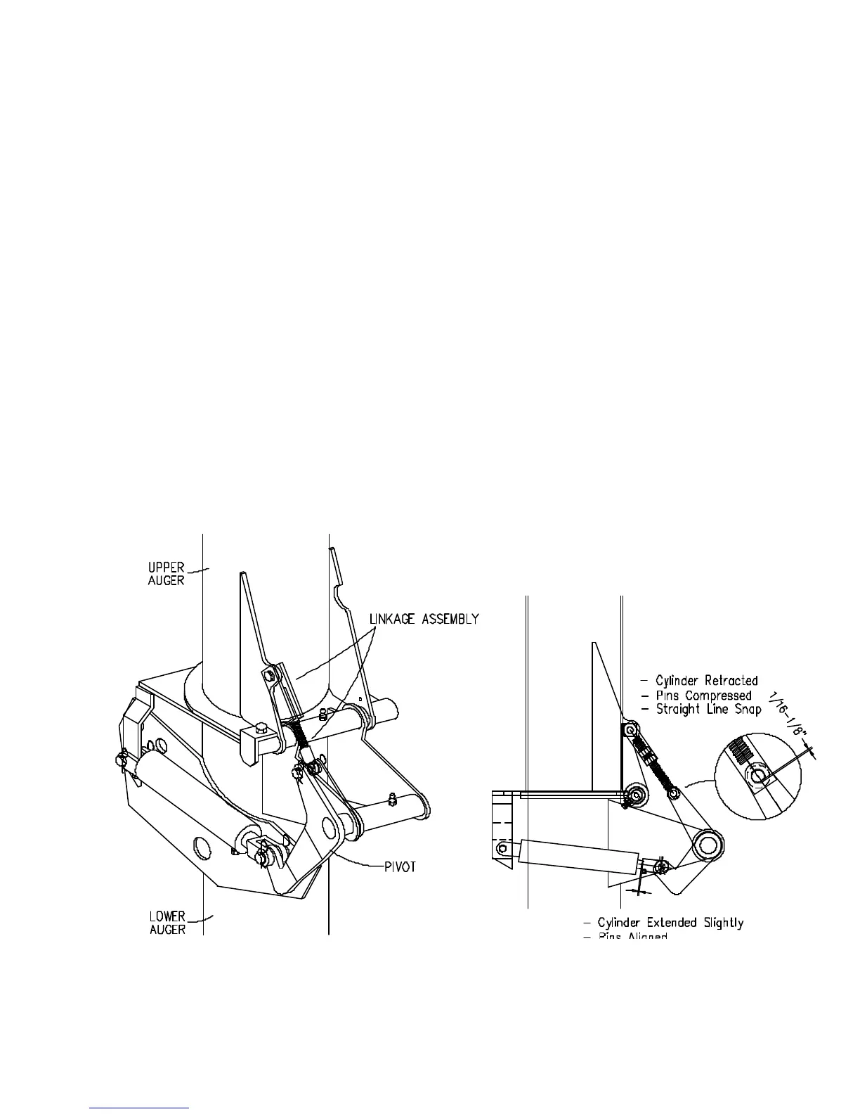
The auger fold linkage is adjusted at the factory and under normal operating conditions
should not require adjustment. Disassembly for service or slight wear in the linkage pins may
necessitate the need for adjustment. The 1/8" compression dimension is necessary for a good
seal at the auger flanges and snap locking at the end of the cylinder stroke.
1. Fold the upper auger into the operating position and clamp flanges to secure.
2. Extend hydraulic cylinder slightly (1/8") to relieve load. Remove T-Bar yoke pin.
3. Retract cylinder to end of stroke.
4. Rotate T-Bar yoke as necessary to position rockshaft arm hole approximately 1/8" past T-
Bar yoke holes when T-Bar linkage and rockshaft arm are in a straight line.
5. Extend cylinder slightly again to line up holes in T-Bar yoke and rockshaft arm. Install pin
and secure with nut. Remove temporary clamp before cycling auger fold operation.
6. Retract hydraulic cylinder. Check for sealing at auger tube flanges and for "straight-line
lock snap" of linkage. Cycle linkage by fully lowering and raising auger tube. Recheck
linkage. Readjust as necessary.
AUGER FOLD ADJUSTMENT
251909
• 06-30-00