1-19
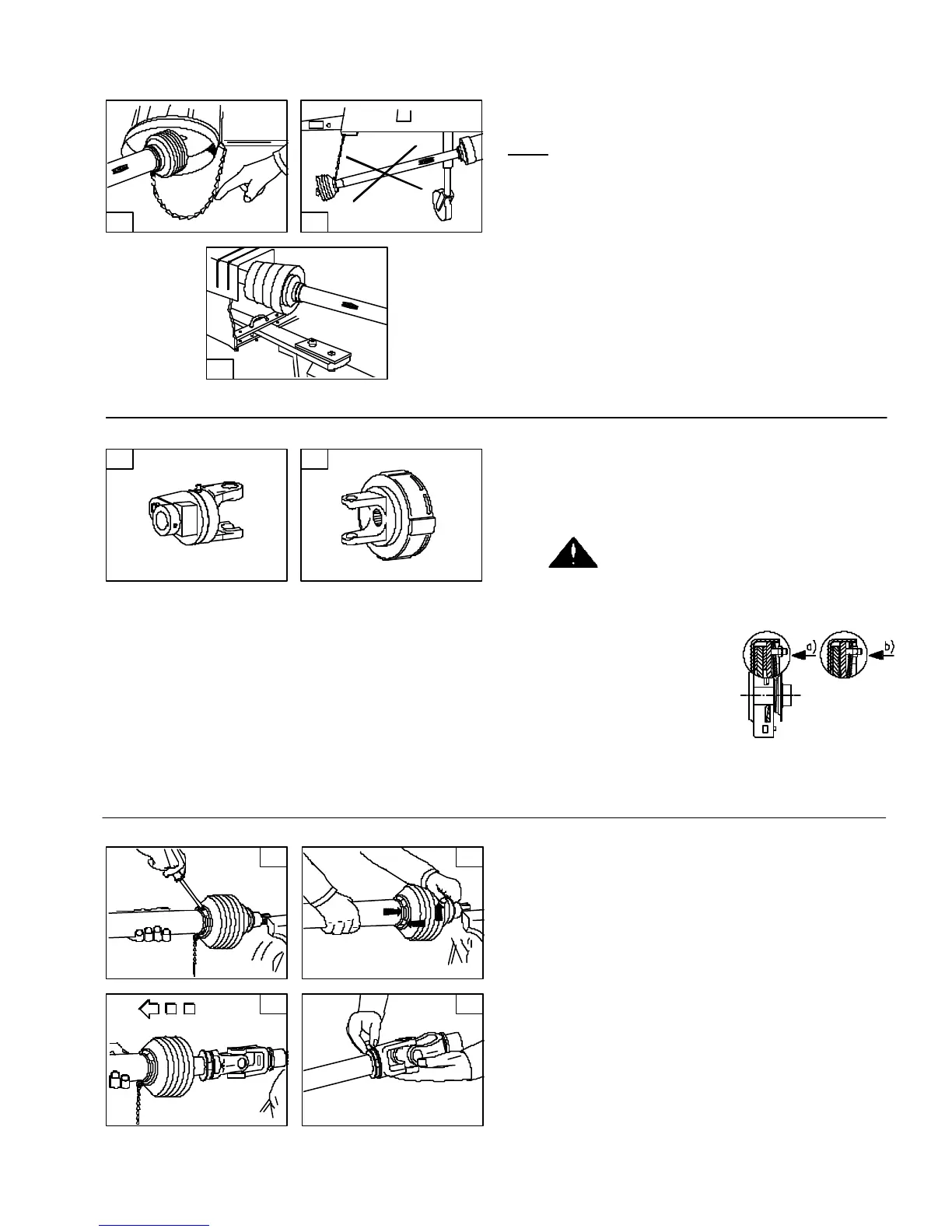
G. Chains (Figs. G1 - G3)
NOTE: The chain is intended to prevent the shield
from rotating against non-moving parts and thereby
preventing shield damage. A properly installed chain
will increase the service life of the shield.
1. Chains must be fitted so as to allow sufficient
articulation of the shaft in all working positions.
Care must be taken to be sure that chain does not
become entangled with drawbar hitch or other
restrictions during operation or transport of
machine.
2. The PTO drive shaft must not be suspended from
the chain.
J. To dismantle guard: (Figs. J1 - J4)
1. Remove locking screw.
2. Align bearing tabs with cone pockets.
3. Remove half-guard.
4. Remove bearing ring.
G2
2. Friction clutches:
When overload occurs, the torque is limited and
transmitted constantly during the period of slip-
ping. Short-duration torque peaks are limited.
Prior to first utilization and after long
periods out of use, check working of disk
clutch.
a. Tighten nuts until friction disks are released.
Rotate clutch fully.
b. Turn nuts fully back.
Now the clutch is ready
for use.
Fig. H2 shown.
Avoid extended and frequent slippage of overload
clutches.
H. Shear bolt and friction clutches (Figs. H1 - H2)
1. Shear bolt clutches:
When the torque is exceeded, power flow is
interrupted due to the bolt shearing. The torque
is re-established by replacing the broken shear
bolt. Use only the bolt specified in the operator's
manual for replacement.
G1
G3
H1
H2
J2
J1
J3
J4
250968H
250968G
250968J