3-6
•
Indicator Mounting:
The indicator is easily attached to the Indi-
cator Mounting Bracket by hooking the top
over the plate and securing the bottom with
two (2) bolts (size# 10 x 24 x 3/4") and nuts.
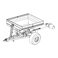
Power Connection:
The power cable should be connected di-
rectly to a vehicle battery or regulated power
supply. The scale end of the power cable is
attached to the J901 connector located on
the bottom panel of the scale.
Connect the RED wire from the power cable
to +12 VDC and the BLACK wire to
GROUND. The indicator is fused internally
at 4 amps.
POWER CABLE CONNECTIONS:
WIRE COLOR WIRE FUNCTIONS
RED Battery (+12 VDC)
BLACK GROUND
ORANGE Remote Alarm Out +
BLUE Remote Input
Remote Alarm Connection:
If a remote 12 VDC alarm is to be used,
connect the +12 VDC side of the alarm to
the power cable orange wire and the
GROUND side (or black wire) to the frame.
The alarm output is fused for a maximum
drain of 10 amps. The remote alarm con-
nection may also be used for motor control
purposes when used with a relay.
Load Cell Connection:
The indicator is designed to operate with
strain gage load cells. The indicator will
normally be supplied with a "J-BOX" cable
going between the scale and the load
cell junction box. Extension Kits are
available from your dealer in various
lengths.
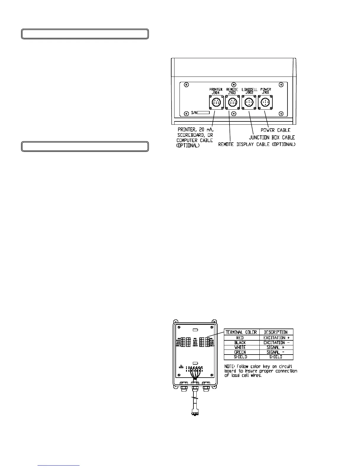
To connect the load cells, attach the
junction box cable to the J902 connector
on the bottom panel of the scale. Con-
nect the load cell cables to the junction
box as shown below.
JUNCTION BOX LOAD CELL
CABLE CONNECTIONS:
• 12-19-01
OPERATION:
It is recommended that the indicator reads
0000 by pressing TARE before unload-
ing the cart in a truck or wagon.
Once the cart is finished unloading, the
exact (negative) amount of grain unloaded
is displayed.
Press TARE to read 0000 again, or press
NET/GROSS to display the amount of
grain remaining in the grain cart.
SCALE BOTTOM PANEL
CABLE CONNECTIONS:
INSTALLATION