1-17
C. Maximum joint angles:
1. Joint (standard type)
Continuous operation 25
o
Short duration 45
o
Stationary 90
o
2. Wide-angle CV joint
Continuous operation 25
o
Short duration 70/80
o
Stationary 70/80
o
Check shaft articulation and clearance zone! Joint
articulations of more than 70/80 degrees leads to
damage.
C2
C1
Contact between PTO drive shaft and tractor or
implement (e.g. three point hitch, drawbar) leads to
damage.
}
(depending on design)
(depending on design)
Ensure equal joint
angles! Switch off
PTO if joint angles
are too large and
unequal!
To avoid injury do not clean, adjust, unclog, or
service PTO driven equipment when the tractor en-
gine is running.
Never exceed the recommended operating speed for
the particular equipment in use.
PTO drive shafts must only be used for their in-
tended purpose.
PTO drive shafts, clutches and freewheels are de-
signed for specific machine types and power require-
ments. They must not be replaced by other models.
NOTE: The tractor and implement manufacturers'
operating instructions.
Ensure that the PTO shaft is securely connected.
This Safety Alert Symbol means Attention!
Become Alert! Your safety is involved!
OPERATING THE PTO
When finishing operation of PTO driven equipment,
shift PTO control to neutral, shut off the engine and
wait until the PTO stops before getting off the tractor
and disconnecting the equipment.
Do not wear loose clothing when operating the power
take-off, or when near rotating equipment.
When operating stationary PTO driven equipment,
always apply the tractor parking brake lock and block
the rear wheels front and back.
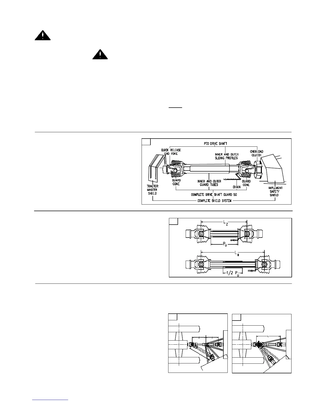
PTO SHAFT & CLUTCH
A. Only use a completely shielded drive
system:
PTO drive systems with complete
shielding, include the tractor master
shield and implement shielding installed
all the time. If any component of the
shield system has been removed for
any reason it, or a repair part, must be
installed before operation.
BB. Note the maximum operating length L
B
!
Try to obtain the greatest possible overlap without
bottoming out in the maximum operating condi-
tion. In its working position, the PTO drive shaft
should not be extended by more than half the
telescoping member overlap P
U
available when
fully compressed L
Z
. (See diagram on inside
cover).
A
250968A
250968C
250968B