Brocade FastIron X Series Chassis Hardware Installation Guide 185
53-1001723-02
Detailed procedure
A
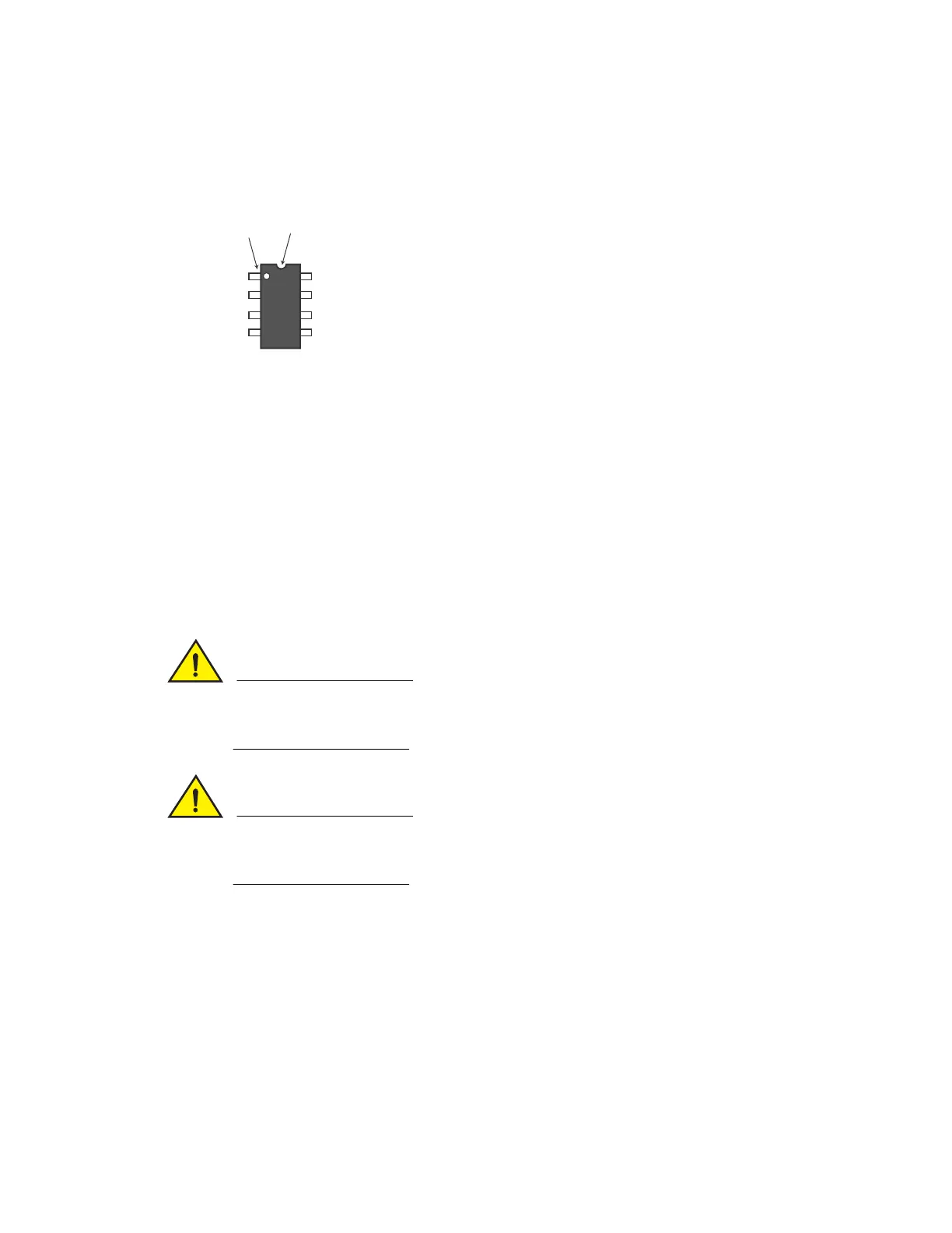
The circular or semicircular indentation on the DIP key indicates the position of lead pin 1. If
the DIP key has a circular indentation, it is aligned with pin 1. The semicircular indentation on
the DIP key is located on the same end as pin 1. Pin 1 is located to the left of the semicircular
indentation.
Align the semicircular indentation on the DIP key with the semicircular cut-out on the DIP
socket. Refer to the appropriate illustration:
• “DIP key insertion for the IPv6 and IPv4 8-port GbE management modules (SX-FI8GMR6
and SX-FI8GMR4)” on page 179
• “DIP key insertion for the IPv6 2-port 10-GbE management modules (SX-FI2XGMR6)” on
page 180
• “DIP key insertion for the IPv4 2-port 10-GbE management modules (SX-FI2XGMR4)” on
page 181
• “DIP key insertion for the IPv6 and IPv4 0-port management modules (SX-FIZMR)” on
page 182
• “DIP key insertion for the FastIron SuperX management modules (SX-FI12GM-4,
SX-FI12GM2-4, SX-FI12GM-6 and SX-FI12GM2-6)” on page 183
Make sure you insert the DIP key so that lead pin 1 goes into the correct hole as shown in the
appropriate illustration. If you accidentally insert the DIP key backwards, the device will not work
and may be damaged when you power it on.
Do not push too hard. If the DIP key does not readily go into the DIP socket, stop pushing and
verify that the lead pins are straightened and properly aligned over the holes, straighten any lead
pins that need straightening, then try again.
5. Re-assemble the device as follows.
• Slide the management module in along the card guide until the ejectors on either side of
the module move close to the module front panel.
• Push the ejectors toward the center of the module. This action will fully seat the module in
the backplane.
• Use a Phillips-head screwdriver to tighten the two screws at either end of the management
module’s front panel.
6. Re-insert the power cable or cables to power on the device, if applicable.
7. Install the software as instructed in the following section.
Pin 1 Semicircular indentation

 Loading...


