Brocade FastIron X Series Chassis Hardware Installation Guide 27
53-1001723-02
Hardware features
1
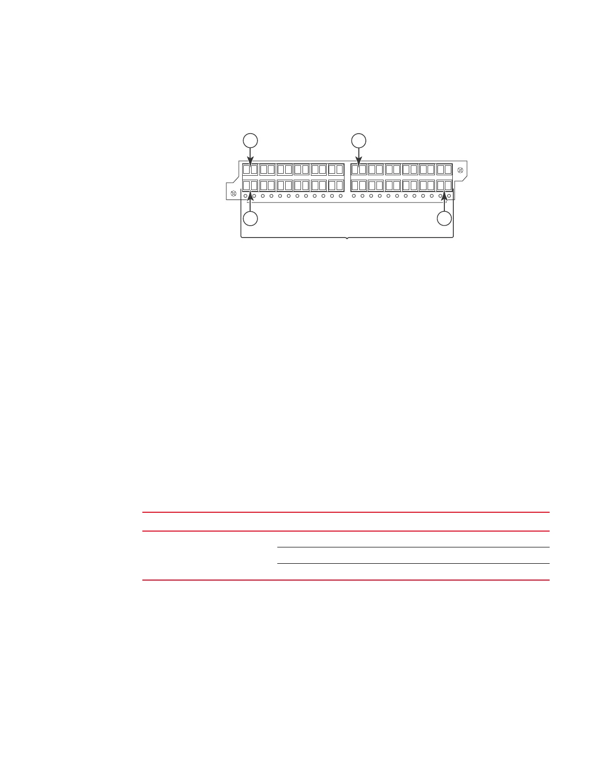
Figure 17 shows the front panel of the IPv4 24-port Gigabit Ethernet fiber module.
FIGURE 17 IPv4 24-port Gigabit Ethernet fiber module front panel
The front panel includes the following control features:
• 24 Gigabit Ethernet fiber ports
• 24 LEDs
LEDs for 24-port fiber module
The fiber module’s front panel includes 24 LEDs that indicate the status of each port. The LEDs are
located beneath the mini-GBIC slots for the ports (refer to Figure 17). The left-most LED is for Port
1, the second LED is for Port 2, and so on.
The ports provide status information using the LEDs described in Table 11.
24-port 100/1000 hybrid fiber interface module
The 100/1000 hybrid fiber module has 24 ports with connectors for mini-GBIC transceivers (also
called Small Form Factor Pluggable (SFP) Multisource Agreement (MSA)-compliant transceivers).
The ports support 100 and 1000 fiber mini-GBICs.
1Port 1
2Port 2
13 Port 13
24 Port 24
TABLE 11 LEDs for 1000 Mbps ports on the 24-port fiber module
LED Position State Meaning
Link or Activity Round LED located
beneath the fiber
connectors
On (Green) A link is established with the remote port.
Blinking The port is transmitting and receiving packets.
Off A link is not established with the remote port.

 Loading...


