Brocade FastIron X Series Chassis Hardware Installation Guide 29
53-1001723-02
Hardware features
1
The mini-GBIC slots support the 100Base and 1000Base fiber cabling listed in “Network
interfaces” on page 30.
Support for 100Base-FX on the 100/1000 interface module
The 24-port 100/1000 fiber interface module supports the following types of SFPs for 100Base-FX:
• Multimode SFP – maximum distance is 2 kilometers
• Bidirectional single mode SFP – maximum distance is 10 kilometers
• Long Reach (LR) – maximum distance is 40 kilometers
• Intermediate Reach (IR) – maximum distance is 15 kilometers
To enable support for 100BaseFX, you must enter the CLI command 100-fx at the Interface level of
the CLI. For CLI command details, refer to the section “Enabling and Disabling Support for
100BaseFX” in the FastIron Configuration Guide.
2-Port 10-Gigabit Ethernet interface modules
The 2-port 10-Gigabit Ethernet modules contain two physical ports, through which you can connect
the Brocade device to other network devices at a speed of 10 Gigabits per second.
The modules have two optical interfaces with LC connectors for 10-Gigabit Small Form Factor
Pluggable (XFP) MSA-compliant transceivers. The transceivers support 10GBase-SR, 10GBase-LR,
and 10GBase-ER fiber optic cabling for LAN PHY or WAN PHY (LAN or WAN module only).
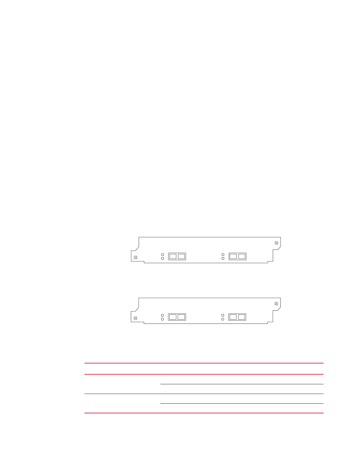
Figure 20 shows the IPv4 2-port 10-Gigabit Ethernet module’s front panel.
FIGURE 20 IPv4 2-port 10-Gigabit Ethernet interface module
Figure 21 shows the IPv6 2-port 10-Gigabit Ethernet module’s front panel.
FIGURE 21 IPv6 2-port 10-Gigabit Ethernet interface module
LEDs for 2-Port 10-Gigabit Ethernet module
The 10 Gbps ports provide status information using the LEDs listed in Table 12.
TABLE 12 LEDs for 10 Gbps ports
LED Position State Meaning
Lnk Top left of
connector
On Fiber port is connected.
Off No fiber port connection exists.
Act Bottom left of
connector
On or Blinking The port is transmitting and receiving traffic.
Off The port is not transmitting or receiving traffic.

 Loading...


