3-30
Confidential
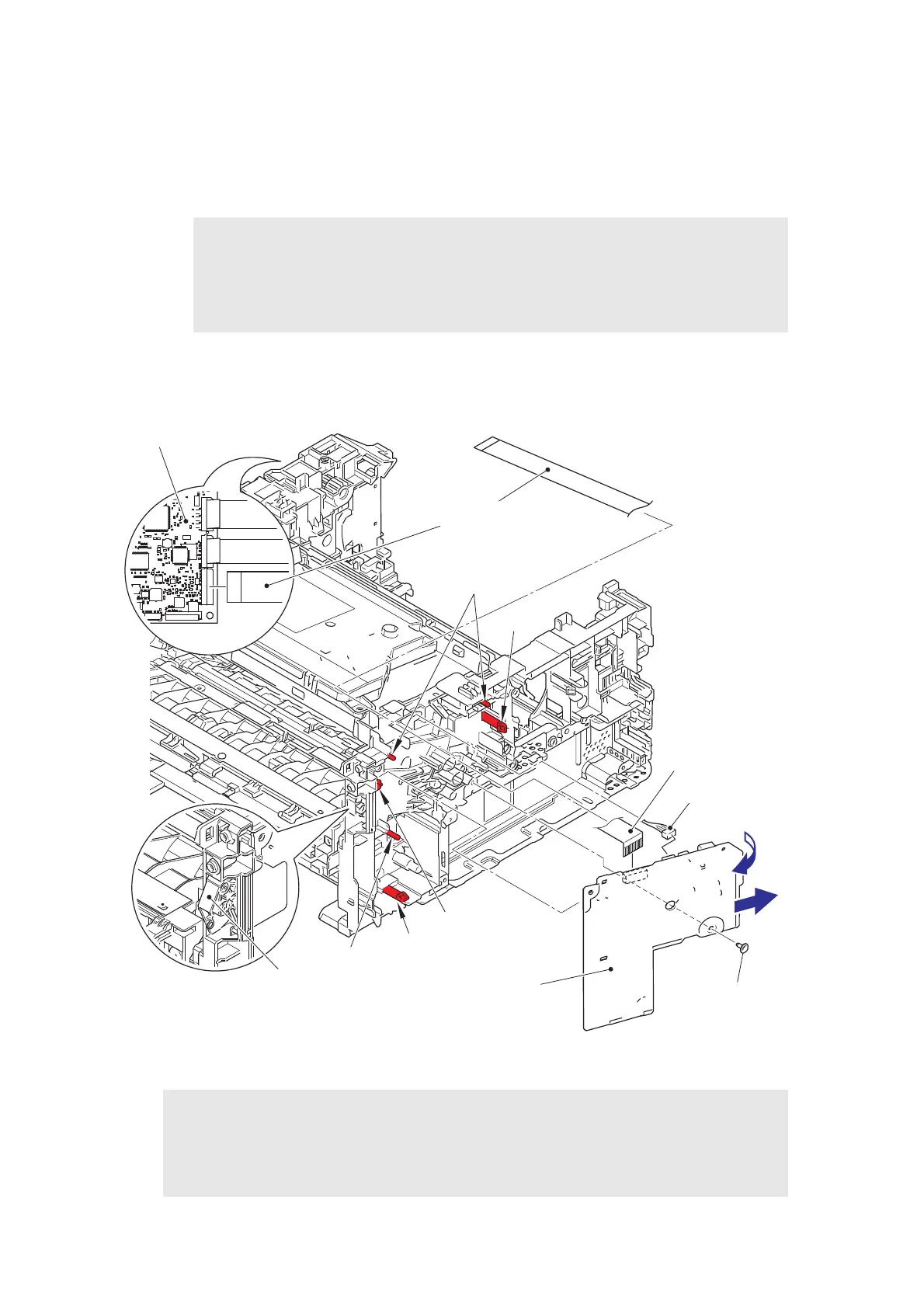
9.13 High-voltage Power Supply PCB ASSY
(1) Disconnect the HVPS flat cable and the registration front/rear sensor PCB harness from
the high-voltage power supply PCB ASSY. Disconnect the HVPS flat cable from the
main PCB ASSY, and release it from the securing fixtures.
(2) Remove the taptite cup S M3x8 SR screw. Release the hooks and pull out the right side
of the high-voltage power supply PCB ASSY in the direction of arrow A to remove it from
the pins. Then pull out the high-voltage power supply PCB ASSY in the direction of
arrow B to remove it from the rib.
Fig. 3-26
Harness routing: Refer to “5. Rear side of the machine”.
Note:
• After disconnecting flat cables, check that each cable is not damaged at its end or
short-circuited.
• When connecting flat cables, do not insert them at an angle. After insertion, check
that the cables are not at an angle.
Assembling Note:
• After attaching the high-voltage power supply PCB ASSY, push electrode springs from
inside of the machine to check that the nothing is caught. (Refer to Fig. 2-6.)
• When attaching the high-voltage power supply PCB ASSY, check that the front cover
sensor lever is on the position in the figure above (jutted forward).
Taptite cup S M3x8 SR
Hook
Registration front/rear
sensor PCB harness
HVPS flat cable
Front cover sensor lever
Main PCB ASSY
High-voltage power
supply PCB ASSY
Hook
HVPS flat cable
Pin
Rib
Pins
<Back side>
A
B
 Loading...