3-46
Confidential
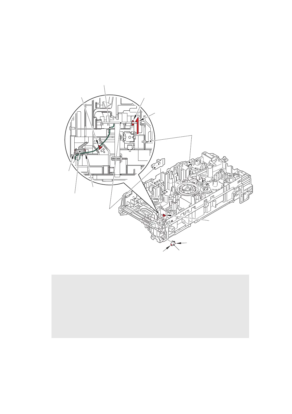
(2) Release the hook A, and remove the eject sensor PCB ASSY from the pin on the main
frame L ASSY.
(3) Release the back cover/duplex tray sensor harness from the guide on the main frame L
ASSY.
(4) Release the hooks B, and remove the back cover/duplex tray sensor from the main
frame L ASSY.
Fig. 3-49
Assembling Note:
• When assembling the back cover/duplex tray sensor, attach it by engaging the hooks B
of the back cover/duplex tray sensor properly.
• If you removed the main shield plate while the fuser unit was attached on the machine,
release the side thermistor harness ASSY and the center thermistor harness ASSY
from the securing fixture of the main frame L ASSY. Then tighten the screw for the main
shield plate and secure each harness in the securing fixture. If the main shield plate is
assembled while the fuser unit is attached to the machine, the side thermistor harness
ASSY and the center thermistor harness ASSY may be caught.
Pin
Eject sensor PCB ASSY
Hook A
Main frame L ASSY
Hook B
Hook A
Hook B
Back cover/duplex tray sensor
Back cover/duplex tray sensor harness
Guide
Back cover/duplex tray sensor
Hook B
Hook B
 Loading...