5-96
Confidential
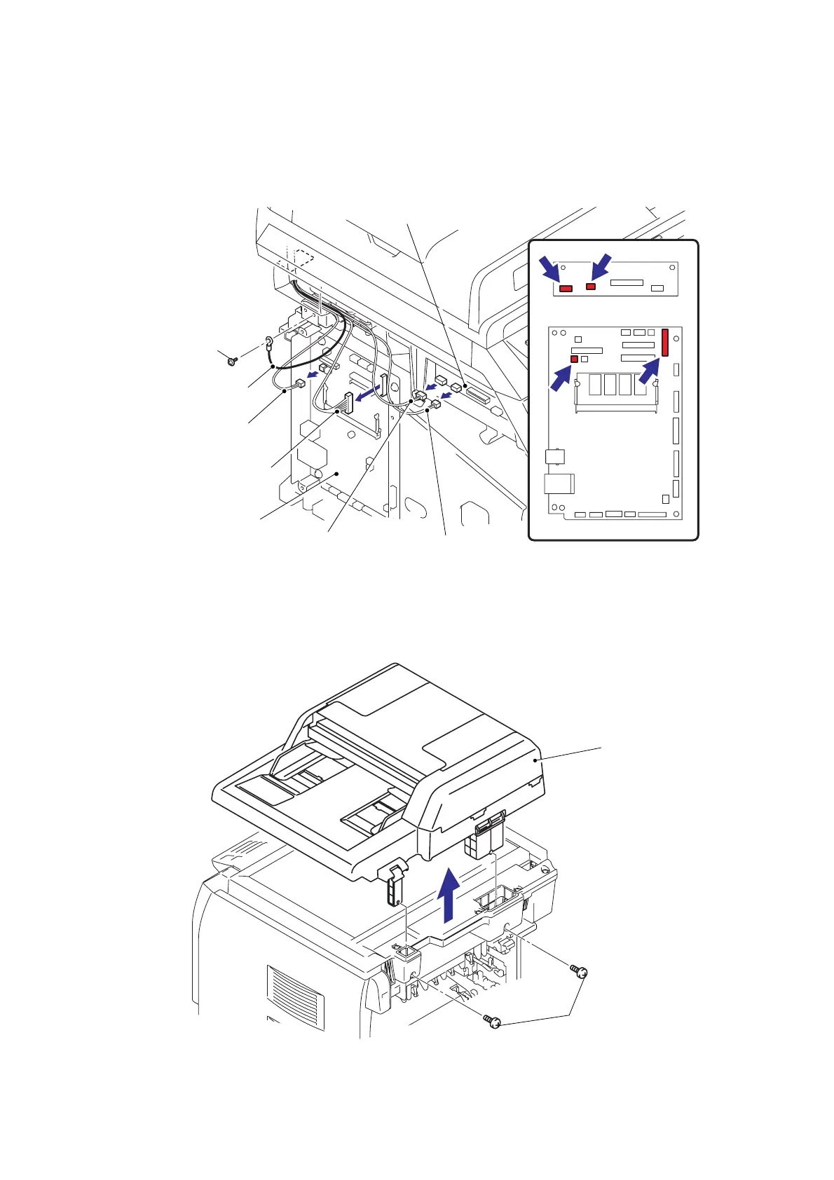
(2) Remove the cup S M3x6 Taptite screw, remove the ADF FG harness.
(3) Disconnect the two Connectors from the Driver PCB.
(4) Disconnect the two Connectors from the Main PCB.
Fig. 5-99
(5) Remove the two bind B M4x12 Taptite screws, and then remove the ADF unit.
Fig. 5-100
Driver PCB
Driver PCB
Connector
(Document eject sensor harness)
ADF FG harness
Connector
(FB cover sensor)
Connector
(ADF relay harness)
Main PCB
Connector
(ADF motor harness)
Main PCB
Taptite cup S M3x6
Taptite bind B M4x12
ADF unit
 Loading...