5-175
Confidential
■ CIS model
9.18.2
Joint Cover ASSY
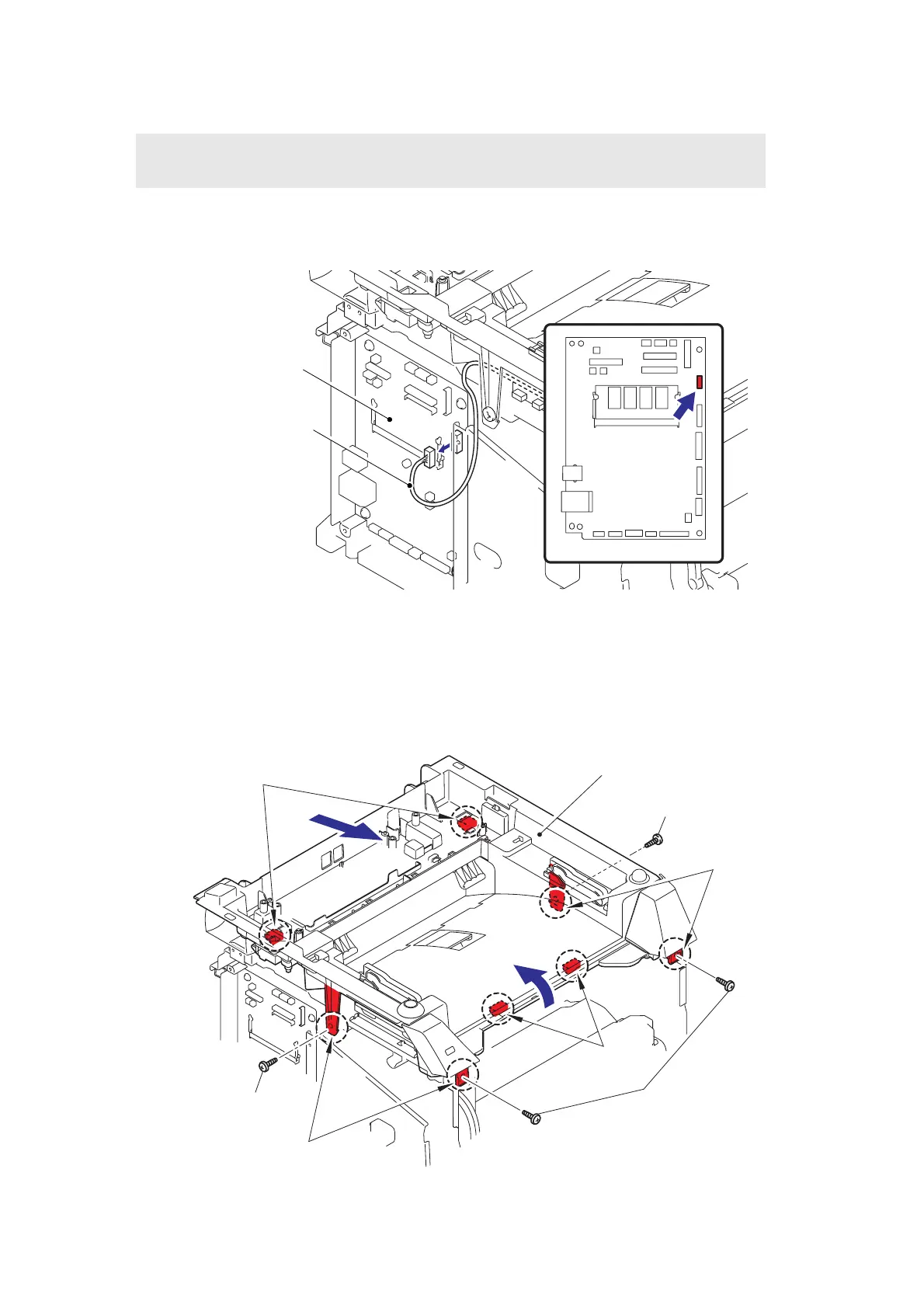
(1) Disconnect the connector of the USB HOST harness ASSY from the Main PCB.
Fig. 5-203
(2) Remove the four bind B M4x12 Taptite screws from the Joint cover ASSY.
(3) Release all Hooks of the Joint cover and lift up the front side of the Joint cover ASSY.
(4) Pull out the Joint cover ASSY’s Bosses to the front side.
Fig. 5-204
Note:
• In the case of the CCD model, refer to "9.18.1 Joint Cover ASSY".
Main PCB
Main PCB
USB HOST harness ASSY
<Left side>
4
Taptite bind B M4x12
Taptite bind B M4x12
Taptite bind B M4x12
<Front side>
Bosses
Hooks
Hooks
Hooks
Joint cover ASSY
3
 Loading...