Confidential
3-57
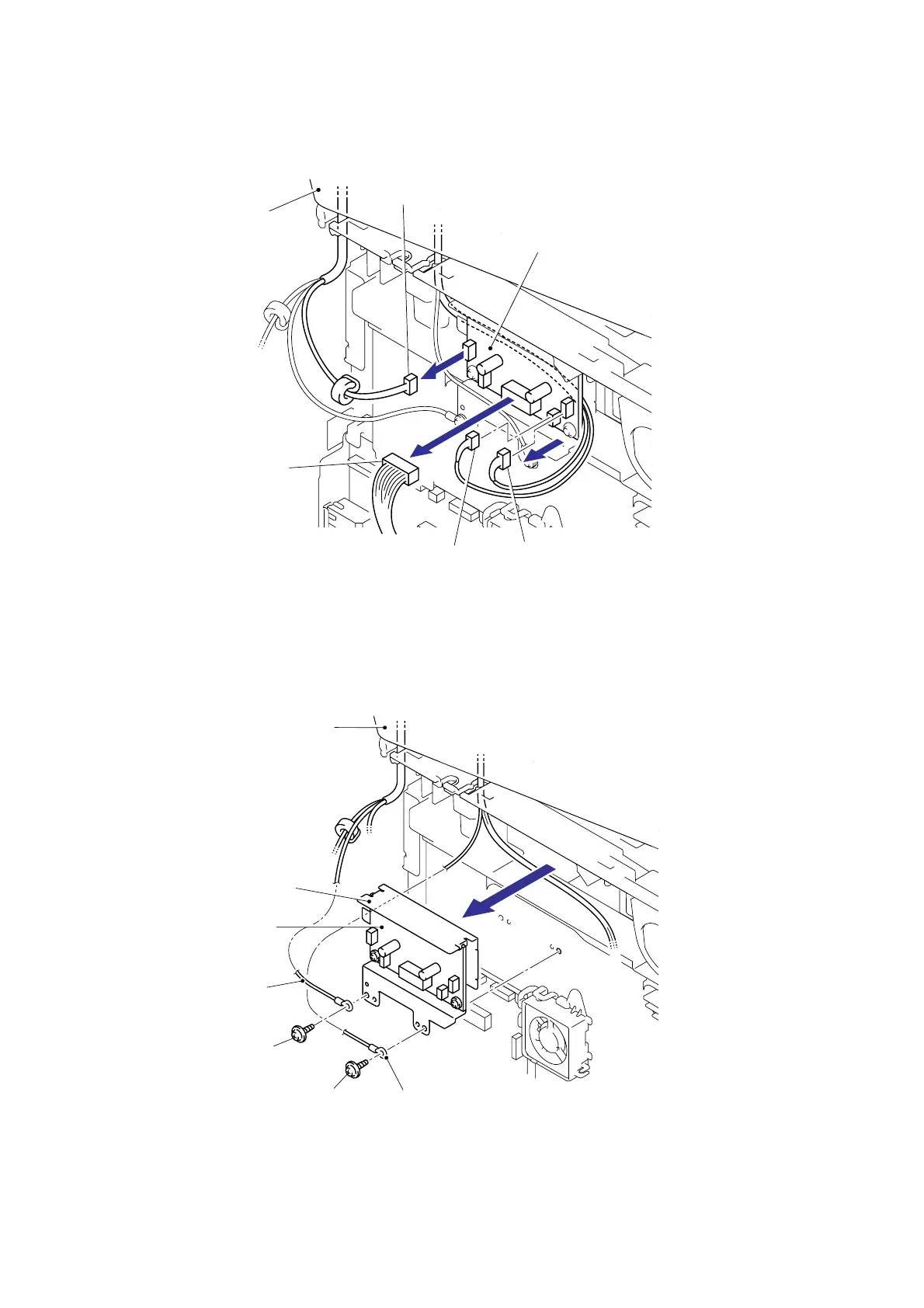
8.17 Driver PCB ASSY
(1) Disconnect the four Connectors (CN1, CN2, CN3, CN5) from the Driver PCB ASSY.
Fig. 3-50
(2) Remove the cup S M3x6 Taptite screw, and then remove the FG harness ADF.
(3) Remove the cup S M3x6 Taptite screw, and then remove the FG harness FB.
(4) Remove the Driver PCB ASSY and Driver PCB shield.
Fig. 3-51
Driver PCB ASSY
CN5
CN1
CN2
CN3
Document scanner unit
Taptite, cup S M3x6
FG harness FB
Document scanner unit
Driver PCB shield
Driver PCB ASSY
FG harness ADF
Taptite, cup S M3x6
<Left side>
<Left side>
 Loading...