Confidential
3-118
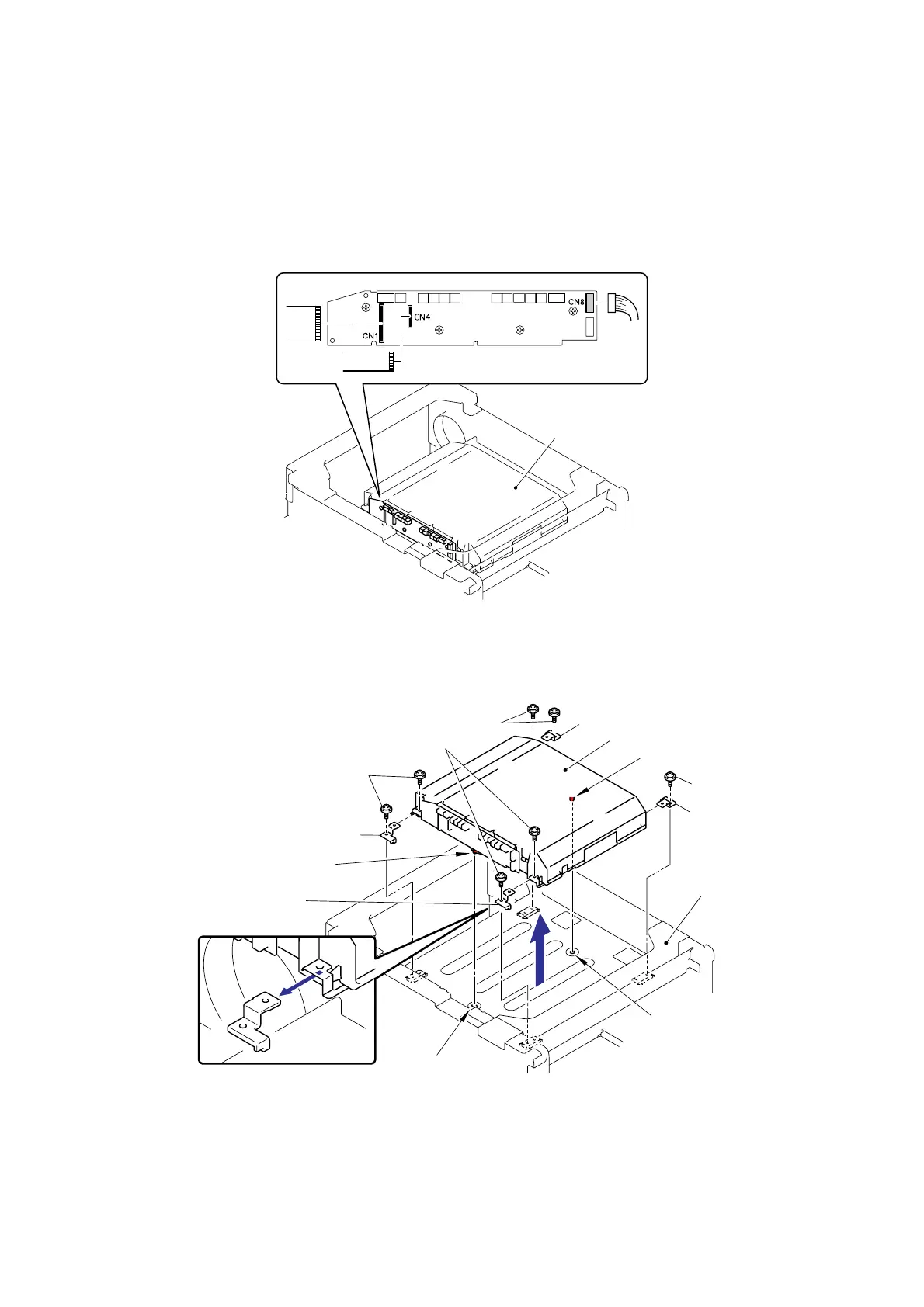
(3) Disconnect the two flat cables (CN1, CN4) and connector (CN8) from the Laser unit.
Note:
- After disconnecting the flat cable(s), check that each cable is not damaged at its end or
short-circuited.
- When connecting the flat cable(s), do not insert it at an angle. After insertion, check that
the cable is not at an angle.
Fig. 3-162
(4) Remove the seven cup S M3x6 SR Taptite screws, and then remove the four Scanner
holders and Laser unit.
Fig. 3-163
Assembling Note:
When assembling the Laser unit with the Scanner holders, ensure to put the positioning
boss of the Laser unit into the positioning hole referring to the figure above.
Laser unit
Scanner holder
Taptite, cup S M3x6 SR
Laser unit
Scanner holder
Frame unit
Taptite, cup S M3x6 SR
Taptite, cup S M3x6 SR
Scanner holder
Taptite, cup S M3x6 SR
<Front>
<Front>
Positioning hole
Positioning hole
Scanner holder
Positioning boss
Positioning boss
 Loading...