II-
6
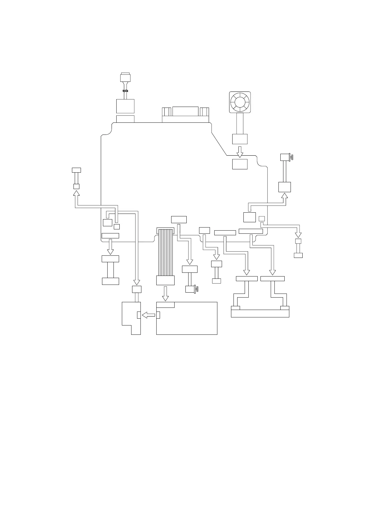
2.2 OUTLINE OF CONTROL ELECTRONICS
Fig. 2.2-1 shows the block diagram of the control electronics. The control electronics consist
of the following components.
CN9
CN10
CN15
CN11
CN8
CN14
CN13
CN7
CN6
CN5
Cutter motor
Cutter home
position sensor
Serial
Fan motor unit
Media feed motor
Media position
detect sensor
Cover open sensor
Thermal head
Power supply PCBDC8V Power PCB ASSY
PC
USB
Key, LED PCB
(SB PCB)
Fig. 2.2-1 Block Diagram of the Control Electronics
2.2.1 Main PCB
This manages all the components. This PCB consists of CPU, EEPROM, USB chip and
motor drivers etc.
2.2.2 Media Position Detect Sensor PCB (Tape Sensor)
This sensor PCB detects the printing start position for the die cut label, and checks existence
of the zebra pattern for the free length label, using reflection type photo sensor.

 Loading...