CHAPTER 5
Data Acquisition Units
61
• A constant light indicates that the battery is driving the frame
The colour indicates the remaining level: from green (full) to red (low)
Flashing red indicates that the battery is nearly empty
• Rapidly flashing red indicates imminent battery failure
Follow Ext. Power Switch
The position of this switch determines the operation of the On/Off button. In the Follow
Ext. Power position, the unit switches on when an external power supply is connected and
off when it is disconnected. This makes it easy to turn the unit on and off when it is part of
a mains powered system.
Chassis Terminal
This is connected directly to the chassis ground of the unit. For more information see
section 4.4.
External Power Input
A LEMO coaxial connector, FFA.00.113, with ground on shield allows the connection of a
10 – 32 V DC power supply or a mains to DC converter. If present, and if necessary,
batteries are charged (one at a time) when external DC is applied. Power Consumption is
nominally 30 W without DC output, and up to 42 W while charging batteries.
5.2.5 Back Panel
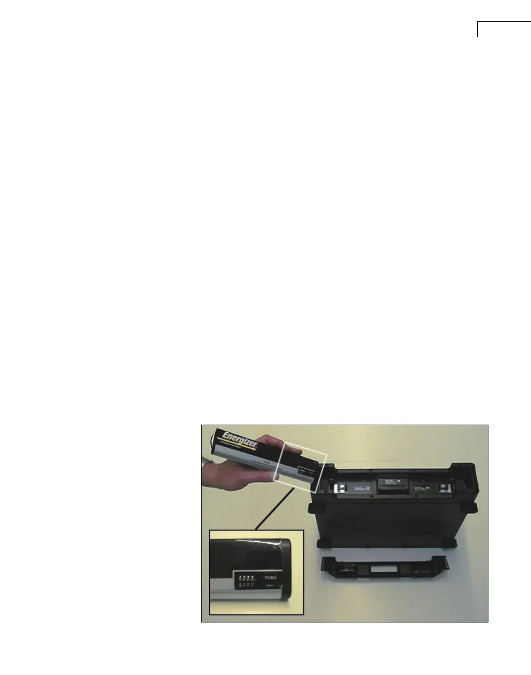
Changing Batteries
The back of the unit has a cover that secures the batteries. To open the cover, lift both locks.
A display on the side of the battery allows you to see the battery’s condition when it is
removed from the unit. For information on power and battery status indicators, see Fig.5.4.
Fig.5.7
Changing batteries
 Loading...