EasyManua.ls Logo

Buderus Logamatic EMS - User Manual

Buderus Logamatic EMS
60 pages
Print Icon
To Next Page IconTo Next Page
Loading...
For trained and
certified installers
Read carefully prior
to installation and
maintenance.
Mounting and Service
Instructions
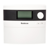
Room controller
Logamatic EMS
6 720 618 477-00.1RS
RC35 user interface
6 720 640 227 - 05/2009 US/CA

Questions and Answers

  • A
    Andrea AdamsSep 13, 2025
    How to solve 'Frost protection w/o remote HZx' on Buderus Network Router?
    • J
      jbrockSep 13, 2025
      If your Buderus Network Router displays 'Frost protection w/o remote HZx', there may be no user interface/remote control unit assigned, even though frost protection is set to room temperature. Check the operating unit parameter and change frost protection to outdoor temperature if needed.
  • L
    livingstontimothySep 15, 2025
    What does 'Room control w/o remote HZx' mean on Buderus Network Router?
    • A
      Amy JohnsonSep 15, 2025
      If your Buderus Network Router displays 'Room control w/o remote HZx', it means there is no RC35 user interface/remote control unit assigned, even though room temperature control is set. Check the operating unit parameter and change to outdoor temperature control if needed.
  • D
    Derek EllisNov 20, 2025
    Why is thermal disinfection unsuccessful in my Buderus Network Router?
    • B
      Brittany ToddNov 20, 2025
      If thermal disinfection is unsuccessful with your Buderus Network Router, it could be due to several reasons. One reason might be excessive water draw during the disinfection period; select a time for thermal disinfection when there is no other demand for heat. Another cause could be a faulty DHW pump; check that the DHW pump is working, for example, by carrying out a function test. Additionally, the sensor might be incorrectly connected, installed, or defective, or there may be a break or short circuit in the sensor lead; in this case, check the sensor connection and lead, ensure the sensor is correctly mounted, and compare resistance values with the characteristic sensor curve. It could also be that the boiler output is too low for heat to be used for other purposes at the same time (e.g...

Summary

Explanation of Symbols and Safety Instructions

Explanation of Symbols and Warnings

Details warning symbols, signal words, and important information icons.

Installation and Use Safety Guidelines

Covers safety during installation, operation, risk of electric shock, scalding, and device damage.

Product Description

Intended Use and System Compatibility

Describes the RC35 control unit's intended application and compatibility with Buderus heating systems.

Technical Specifications

Provides electrical, dimensional, operating, and temperature sensor resistance specifications.

Package Contents

Lists the items included in the RC35 package: user interface, instructions, and mounting kit.

Installation

Installation Location Selection

Provides requirements for installing the RC35 in a reference room or on a boiler.

Mounting and Wiring Connections

Details the process of attaching the wall bracket and connecting the bus cable to the RC35.

Attaching and Detaching the User Interface

Explains the steps for physically mounting the RC35 onto its wall bracket and removing it.

Operating Basics

RC35 Operation Overview

Explains the display, dial, and basic/additional function buttons of the RC35.

Navigating the Service Menu

Guides users on how to access and operate the Service menu for system parameter adjustments.

Service Menu Structure

Details the menus, submenus, and their corresponding functions within the Service menu.

Commissioning

General Commissioning Steps

Outlines the initial steps for commissioning the RC35, including setting language, date, and time.

Commissioning Checklist for Key Parameters

Provides a checklist of important parameters and their settings for system commissioning.

System Commissioning and Handover

Covers final checks, setting boiler controller to "Aut", and explaining operation to the customer.

Entering System Settings

System Data Configuration

Settings for language, units, time/date format, and module installation.

Heating Zone Data Configuration

Settings for activating zones, interfaces, control modes, and systems.

Frost Protection Settings

Options for frost protection, including temperature and room-based triggers.

Domestic Hot Water (DHW) Settings

DHW tank, temperature, and recirculation settings.

Diagnosis

Component Function Testing

Explains how to perform functional tests on individual EMS components.

Monitoring System Values

Describes how to view target and actual values for various heating system components.

Error Message Investigation

Details how to view recent faults, their categories, and system behavior during errors.

Service

Service Interval and Message Management

Covers setting service intervals, viewing, and resetting service messages.

Reset

Resetting System Parameters

Explains how to reset parameters to factory settings, clear fault lists, and reset run time.

Troubleshooting

Troubleshooting Faults and Error Codes

Lists system errors, fault codes, their effects, causes, and remedies.

Service Menu RC35

RC35 Service Menu Flowchart

Provides a flowchart illustrating the navigation paths within the RC35 Service Menu.

Buderus Logamatic EMS Specifications

General IconGeneral
BrandBuderus
ModelLogamatic EMS
CategoryNetwork Router
LanguageEnglish

Related product manuals