MFC/MFM - 31
english
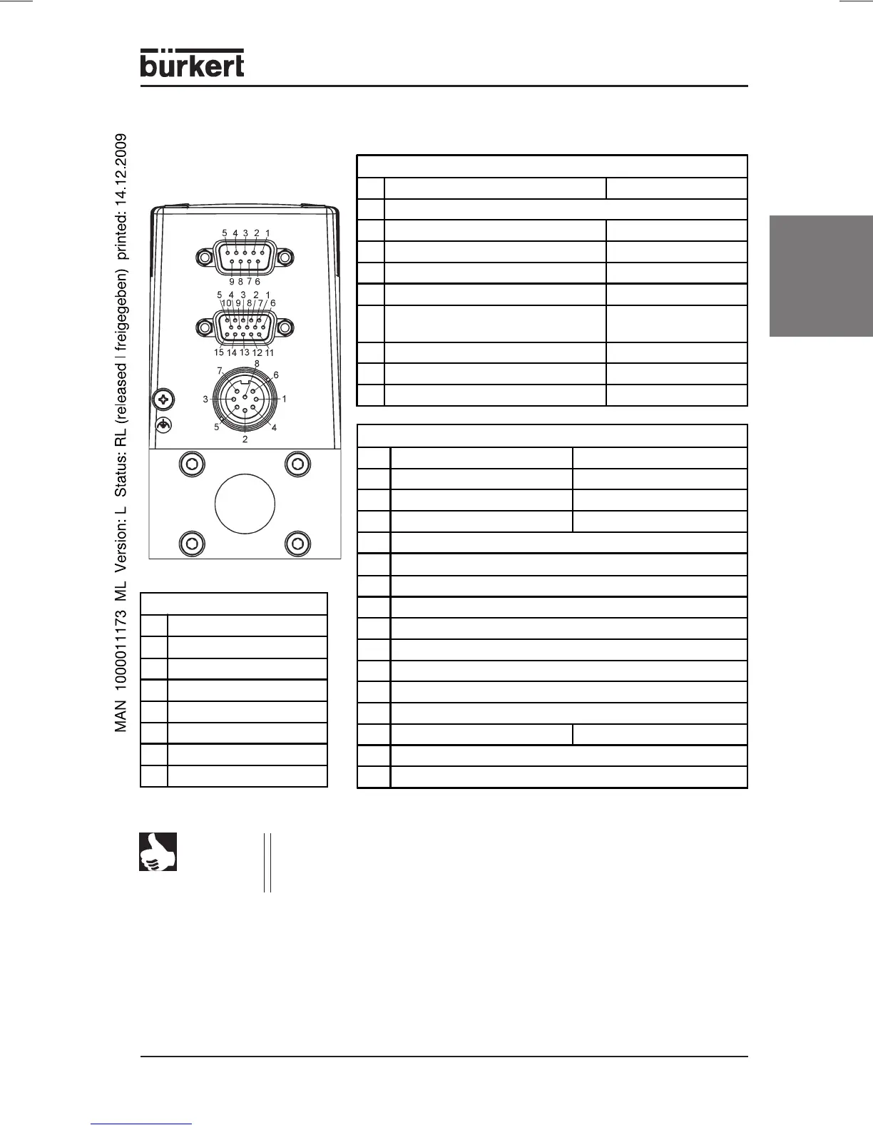
Connection configuration Type 8626 / 8006
NOTE
If a device of Type 8626 / 8006 (built before 2003) is to be replaced
by a new one (from 2003 on), this can be done by using an adapter
(see Appendix A) without additional cabling.
8-pole socket (circular)
1
24V - supply +
2
Relay 1 - C contact
3
Relay 2 - C contact
4
Relay 1 - NC contact
5
Relay 1 - NO contact
6
24V - supply GND
7
Relay 2 - NO contact
8
Relay 2 - NC contact
9-pole Sub-D socket (bus version only)
PROFIBUS DP DeviceNet
1
Shield (FE) functional earth
2
N. C. (not connected) CAN_L data line
3
RxD/TxD-P B-line GND
4
RTS control signal for repeater N. C.
5
GND data transmission potential N. C.
6
VDD
supply voltage + (P5V)
N. C.
7
N. C. CAN_H data line
8
RxD/TxD-N A-line N. C.
9
N. C. N. C.
+15 pole Sub-HD socket
Analog drive Bus version
1
Setpoint input + N. C.
2
Setpoint input GND N. C.
3
Process value output + N. C.
4
Binary input 2
5
12 V output (for factory unse only)
6
RS232 TxD (direct connection to PC)
7
Binary input 1
8
DGND (for binary inputs)
9
For factory use only (do not connect!)
10
12 V output (for factory use only)
11
12 V output (for factory use only)
12
Binary input 3
13
Process value output GND N. C.
14
RS232 RxD (direct connection to PC)
15
DGND (for RS232 interface)