38 - MFC/MFM
english
Bus connection
Types 8626, 8006, 8716, 8706, 8712, 8702, 8711, 8701, 8710 and 8700 are
available as bus versions. Setpoint and process value are received or repeated in
digital form via the bus. One can choose between a PROFIBUS DP and a
DeviceNet connection (see also
Supplement to Operating Instructions for fieldbus
devices
or
serial communication RS 232 / RS 485
).
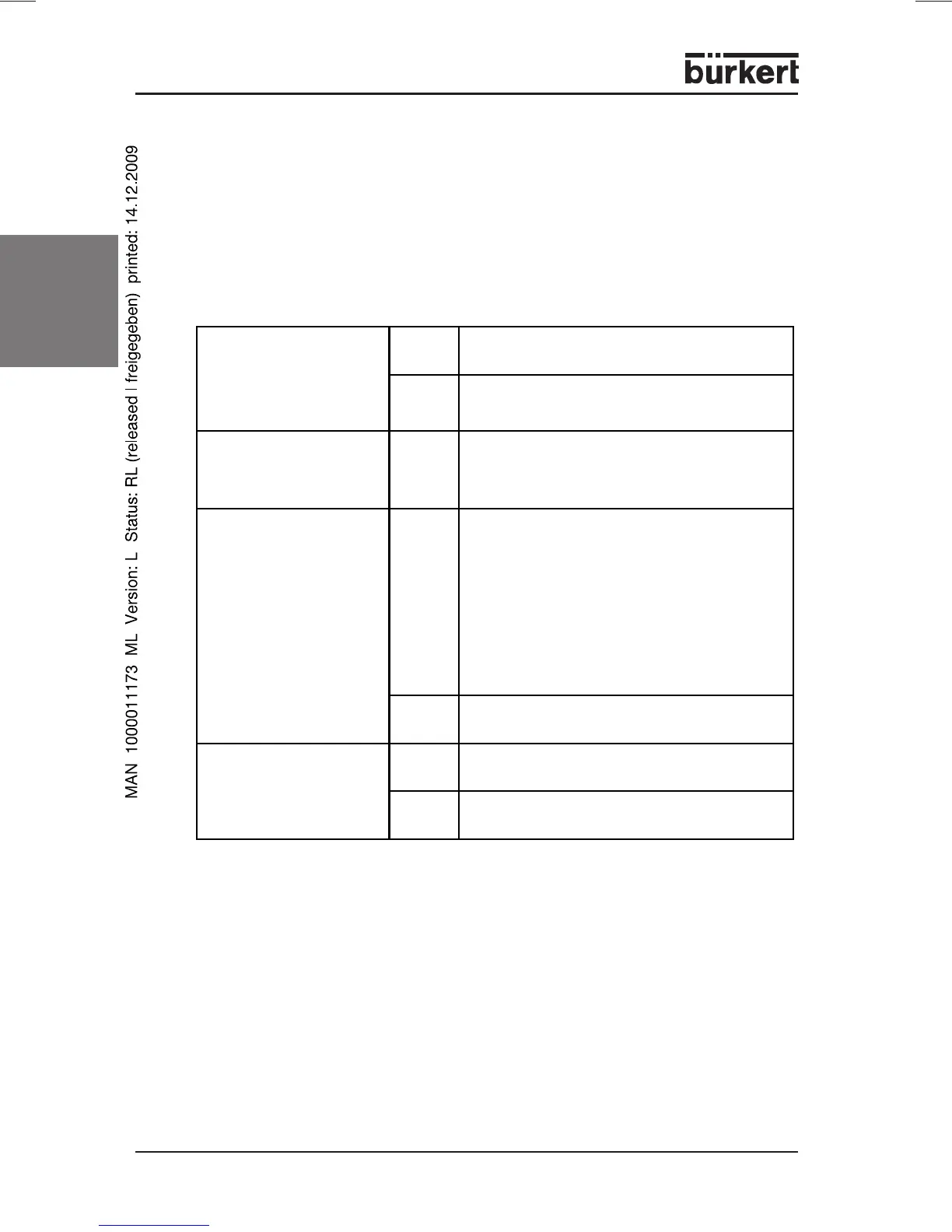
LEDs to indicate the operating mode (deault configuration)
In order to initiate the event in each case, the binary input must be connected for
at least 0.5 s to DGND.
Functions
Binary input 1 Autotune function (not configured with MFM)
Binary input 2 not configured
(not present with 8713 / 8703)
(with second gas calibration - change gas)
Binary input 3 not configured
(not present with 8710 / 8700 / 8711 / 8701 / 8713 / 8703)
Binary inputs (default configuration)
POWER LED lights The device is supplied with operating
voltage
flashes Autotune function activated
(green)
COMMUNICATION LED lights The device communicates via bus or RS-
interface.
(yellow)
LIMIT (y) LED lights With MFC:
indicates that the correcting variable of the
valve has almost reached 100 %. In
practice, this usually means that the
pressure at the controller is insufficient to
realize the desired flow rate.
With MFM:
indicates that the process value has almost
reached the nominal flow rate.
(blue)
flashes The device is in an operating mode other
than control or Autotune.
ERROR LED lights Not a serious error, e.g. Autone not
completed successfully or faulty LED.
(red)
flashes Serious error, e.g. sensor breakage or faulty
internal voltage supply.