47
Type 8682, 8693
english
Installation
5.3 Terminal Assignment for Cable Gland - Process Controller Type 8693
First connect the process controller as described in the chapter entitled “ → 5.2 Terminal Assignment for Cable Gland - Posi-
tion Controller Type 8692”.
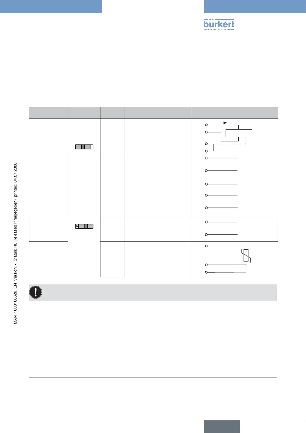
5.3.1 Terminal Assignment when Selecting the Process Actual Value Input
Input type* Switch** Terminal Configuration External circuit
4 – 20 mA
- internally sup-
plied
Switch
on left
1
2
3
4
+ 24 V transmitter input
Transmitter output
Bridge after GND (GND from
3-wire transmitter)
GND
GND
1
2
3
4
Transmitter
I
Frequency
- internally sup-
plied
1
2
3
4
+ 24 V sensor supply
Clock input +
Not assigned
Clock input - (GND)
1
2
4
+ 24 V
Clock +
Clock - (GND)
4 – 20 mA
- externally sup-
plied
Switch on
right
1
2
3
4
Not assigned
Process actual +
Process actual -
Not assigned
2
3 GND
+ (4 – 20 mA)
Frequency
- externally sup-
plied
1
2
3
4
Not assigned
Clock input +
Not assigned
Clock input -
2
4 Clock -
Clock +
Pt 100
(see information
below)
1
2
3
4
Not assigned
Process actual 1 (current feed)
Process actual 2 (GND)
Process actual 3 (compensa-
tion)
Pt 100
2
3
4
For reasons of wire compensation connect the Pt 100 sensor via 3 wires.
Always bridge Terminal 3 and Terminal 4 on the sensor.
When the power supply voltage is applied, the positioner is operating.
Now implement the required basic settings and activate automatic adjustment of the positioner as described in the chapter
→
entitled “Initial Start-up” or “Starting and Setting Up the Process Controller Type 8693”.
* Can be adjusted by software (see chapter entitled “Specifying the Basic Settings”)
** The switch is situated on the terminal board of the positioner (see Fig. 4)