59
59
EN
6 Installation
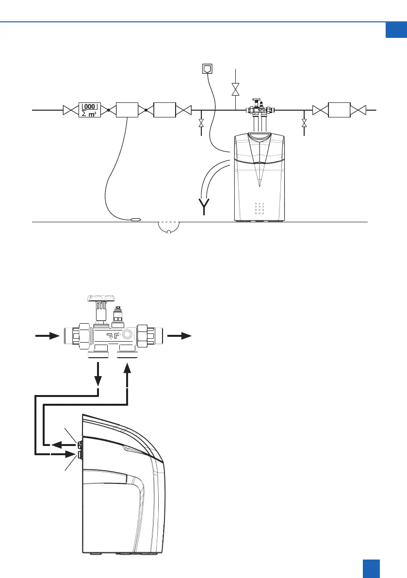
6.1 Installation diagram
Pressurereducer,andme-
tering unit may be required
depending on operating
conditions
AQA stop
Pressure
reducer
Floor
sensor
Floor
drain
Sample cock
Filter
Dosing
unit
Connect the unit as shown in the adjacent
diagram.
A bypass is integrated into Multiblock X.
Theunitcan be installed in horizontal or vertical
pipelines.
Follow the separate installation instructions;
otherwise the warranty is void if the unit becomes
damaged.
Flush out any dirt particles by opening the hand-
wheel on the Multiblock.
Connect a corrugated hose to the Multiblock outlet
andthenconnectthistothehardwaterinlet (6).
Observethearrowindicatingthedirectionofow!
Connect a corrugated hose to the Multiblock inlet
and form a watertight seal with the softened water
outlet(5).
Multiblock X
5
6
Inlet
to 6
Outlet
from 5