PMW20
177
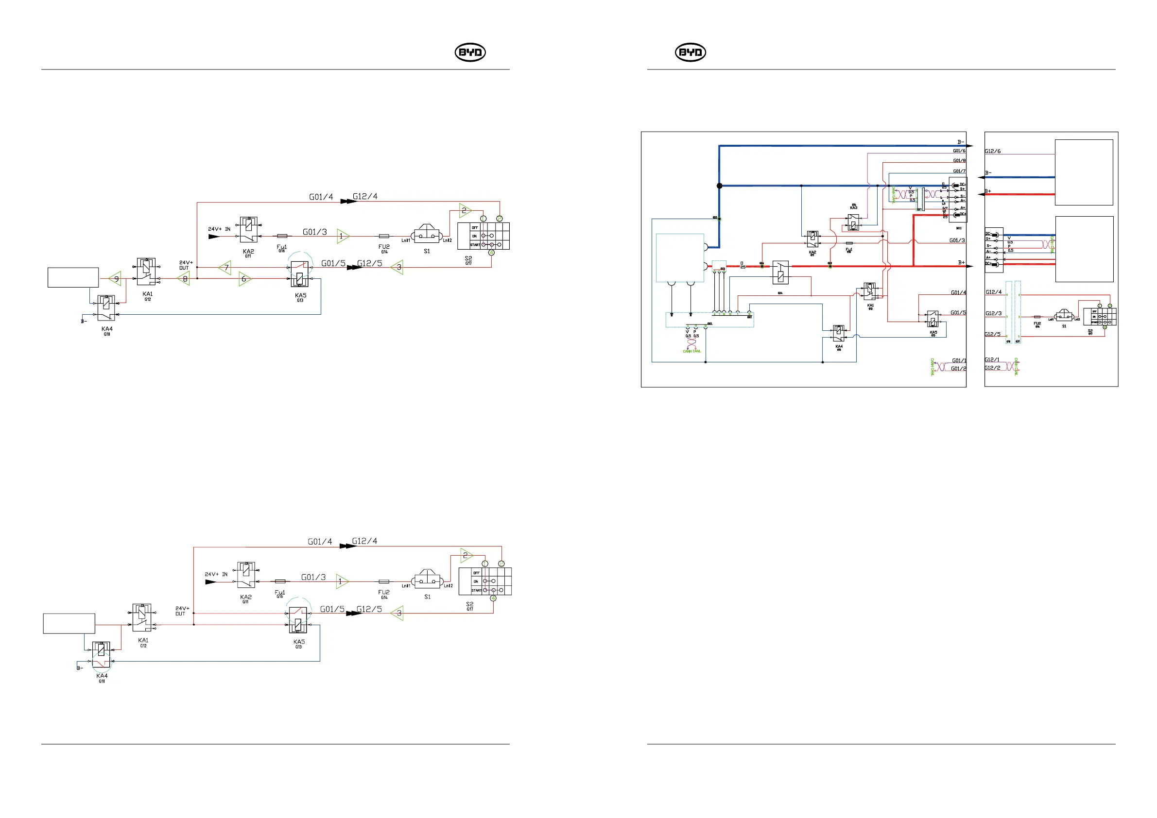
8.9.1.8 Charging Process(National Standard Port)
Internal Battery Charger or Entire Forklift
●Connect the charger BCC, charging port inputs 24V power (A +, A- pin outputs 24V
power supply), the normally open contact of BMS relay KA1 pulls in, the BMS is
energized, and the positive pole of the charge and discharge contactor coil is energized.
●Connect the charging pile BCC, charging port inputs 24V power (A +, A- pin outputs 24V
power supply), the charging relay KA2 and the ignition switch circuit are disconnected,
the entire forklift cannot be powered on.
●The BMS collects the voltage and temperature information of the battery. If there is no
abnormality in the battery, it controls the charging and discharging contactor KM1 to pull
in and connect the positive and negative electrodes of the battery to the positive and
negative electrodes of the charger to start charging. If there is abnormality in the battery,
the contactor does not pull in, and the charger cannot charge the battery.
+15V
-15V
KM1
Recharge Socket
Entire
Forklift
System
Charger
B-
B+
PMW20
176
8.9.1.7 Sleep Process
●The entire forklift is powered on and is stationary without any operation. As shown in
Figure 5, the current trend direction of the entire forklift is 1——2——3——7——8——9
(Ignition switch S1 second gear).
●During the discharge process, if the BMS detects that the discharge current is below
5A for 60min through the current hall or samples that the minimum single-section
voltage is less than or equal to 2.5V, then it enters the low power consumption mode
and the BMS G02-12 pin does not pull down the output. The main contactor KM1 is
disconnected, and at the same time the G02-3 pin pulls down the output. When the
sleep relay KA4 is disconnected, the ignition relay KA5 loses its negative pole and the
ignition relay KA5 contact is disconnected, the entire forklift loses power and enters
sleep status, as shown in figure 6.
SM-PMW202020001-EN
SM-PMW202020001-EN
Ignition Switch
Emergency Stop Switch
Ignition Switch Fuse
Positive Current Fuse 15A
Ignition Relay
Charging Relay
Relay of the Power Manager
Sleep-mode Relay
Sleep-mode Relay
Relay of the Power Manager
Charging Relay
Positive Current Fuse 15A
Ignition Relay
Ignition Switch Fuse
Emergency Stop Switch
Ignition Switch
Battery
Backup
Unit
Hall Current
Current
Hall
Signal
Voltage
Sampling
Temperature
Sampling
Charging-discharging Contactor
Power Manager A BMS1
Sleep-mode Relay
Charging Relay
Positive Current Fuse 15A
Controller Relay
Relay of the Power Manager
Ignition Relay
Ignition Switch Fuse
Emergency Stop Switch
Ignition Switch
Power Manager
Fig. 5
Fig. 6
Power Manager