PMW20
179
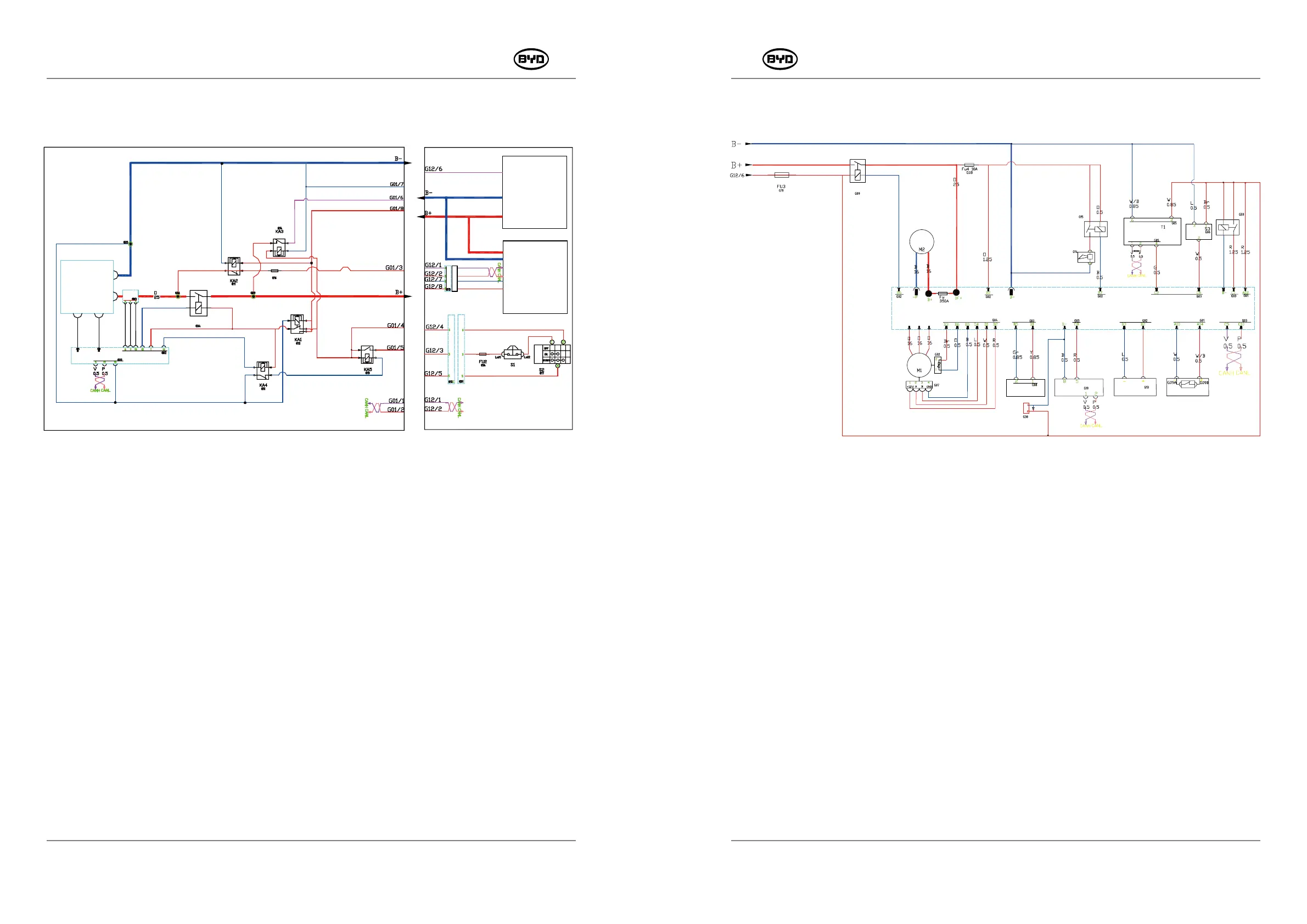
8.9.2 Control System
●If the charging and discharging contactor KM1 inside the battery box pulls in, the
contactor KM3 has 24V power at the battery box end.
●If the controller relay pulls in and the main controller C1 hole gets 24V voltage, the
controller logic circuit starts to work.
●The controller starts the self-inspection work. If there is no serious fault, the main
controller controls the contactor KM3 to pull in, and the controller B + gets electricity.
Contactor coil KM3:
●The contactor coil used on the controller is 24V, the coil power is provided by the
controller B6 hole and the battery G01-6 hole. When the coil is energized, the main
contactor contact pulls in, and the 24V power from the battery box will reach B +.
●When the handle is placed vertically for a period of time without use, the main contactor
KM3 will disconnect automatically. When the handle is returned to the proper position
again, the contactor KM3 will pull in automatically.
PMW20
178
8.9.1.9 Charging Process (On-board charger)
Internal Battery
Charger or Entire Forklift
+15V
-15V
KM1
Entire
Forklift
System
Forklift
-mounted
Charger
B-
B+
●When the on-board charger is connected to the power grid, the auxiliary power supply
outputs 24V, and the power is supplied through (G13-1, G13-2) —— (G12-8, G12-7)
—— (G01-8, G01-7). The normally open contact of BMS relay KA1 pulls in, the BMS
and the positive pole of the charge and discharge contactor coil are energized.
●When the on-board charger is connected to the power grid, the auxiliary power supply
outputs 24V, and the power is supplied through (G13-1, G13-2) —— (G12-8, G12-7)
—— (G01-8, G01-7). The charging relay KA2 and the ignition switch circuit are
disconnected, and the entire forklift cannot be powered on.
●The BMS collects the voltage and temperature information of the battery. If there is no
abnormality in the battery, it controls the charging and discharging contactor KM1 to
pull in and connect the positive and negative electrodes of the battery to the positive
and negative electrodes of the on-board charger to start charging. If there is
abnormality in the battery, the contactor does not pull in, and the on-board charger
cannot charge the battery.
KM3
1.37Kw
120
?
1.2Kw
24VDC
KEY Fuse
U V W
SM-PMW202020001-EN
SM-PMW202020001-EN
Main Contactor
Lift Motor
Drive Motor
Motor Brake
Display
Lowering
Solenoid
Valve
COMBIACX Main Controller CT1
Limit Switch of the Fork
Horn
Horn
Relay
Quick
Reverse
Handle
Handle
Limit
Switch
Time
-
delay
Relay
Release
Motor
Brake
Ignition Switch
Emergency Stop Switch
Ignition Switch Fuse
Ignition Relay
Relay of the Power Manager
Sleep-mode Relay
Positive Current Fuse 15A
Controller Relay
Charging Relay
Charging-discharging Contactor
Hall
C
urrent
Current
Hall
Signal
Voltage
Sampling
Temperature
Sampling
Power Manager A BMS1
Battery
Backup
Unit