Do you have a question about the C-COR Flex Max901e and is the answer not in the manual?
Provides a general introduction to the Flex Max901e 1GHz amplifiers and their key features.
Details the various part numbers and model configurations for trunk and bridger amplifiers.
Explains manual notation, warnings, cautions, and outlines FCC/CE compliance.
Lists relevant C-COR documents and necessary tools/materials for procedures.
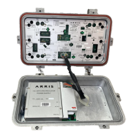
Identifies and describes key physical interface points on the amplifier unit.
Details the Value Max Transponder and its LED status indicators.
Provides visual guides for the proper insertion of plug-in accessories.
Highlights key factors and considerations before performing an amplifier upgrade.
Lists required tools and details RF module replacement steps.
Provides instructions for safely opening and closing the amplifier housing.
Steps to prepare and inspect the housing before installing the amplifier.
Describes various methods for mounting the amplifier housing.
Instructions for attaching cables and properly closing the amplifier housing.
Instructions for configuring the power supply and testing voltage levels.
Methods for calculating carrier levels and compensating for temperature.
Details pre-configured settings for common 1GHz and 870MHz operations.
Step-by-step guides for balancing the forward and return signal paths.
Introduction to troubleshooting and lists necessary tools and materials.
Methods for checking signal outages and diagnosing power supply problems.
Procedures to verify amplifier balance and gain in forward and return paths.
Lists tools, describes inspections, and provides fuse replacement instructions.
Steps for installing return switches and replacing the RF module.
Instructions for replacing the power supply and managing the transponder.
Procedures for safely replacing the amplifier housing.
Compares features of Flex Max901e with older 700/800/900/901 series amplifiers.
Provides recommended FM901e upgrade paths for older series amplifiers.
Detailed technical specifications for Flex Max901e Trunk Amplifiers.
Detailed technical specifications for Flex Max901e Bridger Amplifiers.
Physical specs for housings and technical specs for the transponder.
Illustrates the functional blocks of the trunk amplifier.
Illustrates the functional blocks of the bridger amplifier.
Explains how to use tables to select appropriate accessories for balancing.
Guidance on installing accessories and information on system upgrades.
Tables detailing insertion loss and cable simulation values for accessories.
Details the warranty periods for various C-COR product categories.
Outlines the limitations and exclusions of the C-COR warranty.
Fields for recording system map details and signal information.
Sections for recording measured signal levels and power supply details.
| Output Level | 50 dBmV |
|---|---|
| Input Return Loss | 16 dB |
| Output Return Loss | 16 dB |
| Power Supply | 60 VAC |
| Operating Temperature | -40 to +60 °C |