5
1502154 Rev D Configuration 5-17
Forward Balancing Procedure
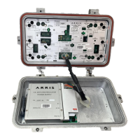
Refer to Figure 2.1 and Table 2.1 for control and accessory locations.
➤ To balance the forward path
1. Determine the System Forward High and Low Balancing Carrier Levels:
■ If bandedge carriers are used for balancing, copy the amplifier bandedge carrier
output levels from the system map to the Map Signal Information table on the
Amplifier Data Sheet.
■ If other than the bandedge carriers are used for balancing, calculate the balancing
carrier levels (see Calculating Balancing Carrier Levels on page 5-6 if not already
done). Record these levels in the Map Signal Information table on the Amplifier Data
Sheet.
2. Temperature compensate the System Forward High and Low Balancing Carrier Levels:
3. Set the amplifier to factory-aligned condition as follows:
a. Set the ALC/MAN switch to the MAN position.
b. Ensure that an SEQ-0 or SEQ-1G-00 is installed in the STATION FWD EQ location
and an NPB-000 is installed in the STATION FWD PAD location.
c. Ensure the ALC PAD location contains a factory-installed NPB PAD for an NTSC pilot
channel or an NPB PAD determined by the tables on page 5-15 for a QAM pilot
channel.
d. Install the interstage EQ, BRIDGER EQ/PAD, and P5/P6 FWD PAD as specified by
the system design specifications (available from the system manager).
Temperature Need
Compensation?
Procedure
below 50
°F (10°C)
or
above 90
° F (32°C)
Yes Record the current air temperature on the Amplifier Data
Sheet.
Perform temperature compensation according to
Temperature Compensation on page 5-6.
Record the compensated values in the System High and Low
Balancing Carrier Levels calculation boxes as shown in
Steps 4 and 5.
If the air temperature changes more than 20•F (11•C) while
balancing the amplifier, recalculate the temperature
compensation.
between 50 and 90
°F
(10 and 32
°C)
No Record the current air temperature on the Amplifier Data
Sheet.
Copy the Forward High/Low Balancing Carrier Levels from
the Map Signal Information table on the Amplifier Data Sheet
to the calculation boxes in Steps 4 and 5.
Note Distribution accessories are reversible. The recessed groove on the top of a
directional coupler indicates the high-loss leg. Ensure that the accessory is installed
with the correct orientation to get the required level at each port.