5
5-18 Flex Max901e 1GHz Trunk and Bridger Amplifiers 1502154 Rev D
e. Install the distribution accessories as specified on the system map. Refer to the
distribution accessories table in Accessory Tables on page D-6 as needed.
f. If no distribution accessories are to be installed, ensure that factory-installed jumper
wires are present. Install jumper wires if absent.
g. Ensure that all unused, active ports are terminated with a 75Ω impedance.
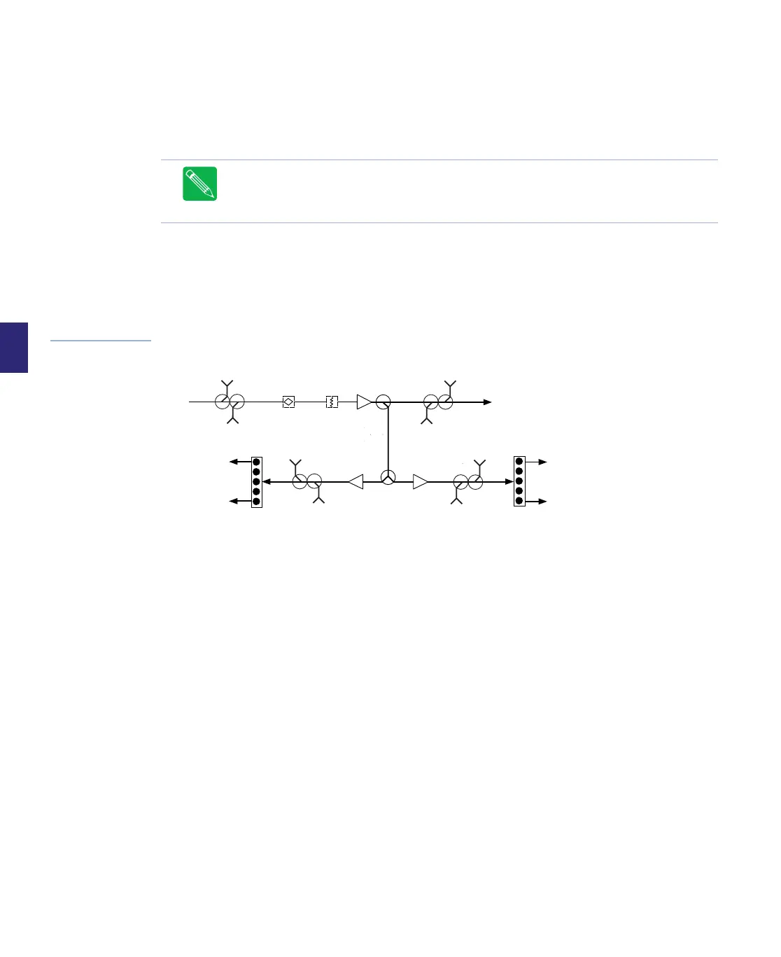
4. Equalize the RF signal:
a. Connect the signal level meter to:
■ the internal/external PORT 4 FWD O/P TP for FMT1 amplifiers.
■ the internal/external P5/P6 FWD O/P TP for FMB1 amplifiers.
Figure 5.9
Simplified Forward
Path Block Diagram
b. Measure the signal levels of both forward balancing carriers. These levels will be
referred to as the Measured High and Low Balancing Carrier Levels. Record these
levels as shown in the box that follows. Calculate System Tilt, Measured Tilt, and
Equalization Value.
Note Testpoints are –20dB or –25dB referenced to the associated port input or output
level as indicated by the housing label.
Note Do not terminate the unused port testpoint as it can affect testpoint accuracy.
Port 1
Port 2
Port 3
Port 4
Port 5
Port 6
STATION
FWD EQ
STATION
FWD PAD
STATION
FWD EQ
PORT 4
REV I/P
TP
PORT 4
FWD O/P
TP
PORT 2/3
REV
I/P TP
PORT 2/3
FWD
O/P TP
PORT 5/6
REV I/P
TP
PORT 5/6
FWD O/P
TP
PORT 1
REV O/P
TP
PORT 1
FWD I/P
TP