4
4-14 Flex Max901e 1GHz Trunk and Bridger Amplifiers 1502154 Rev D
Cable Attachment
➤ To attach cable
1. For each port, use a #2 Phillips screwdriver to turn the centerseizure screw clockwise until
it seats, loosen the centerseizure screw two full turns (no more), and remove the cap or
threaded plug from the cable entry port. Refer to Figure 4.8 as necessary.
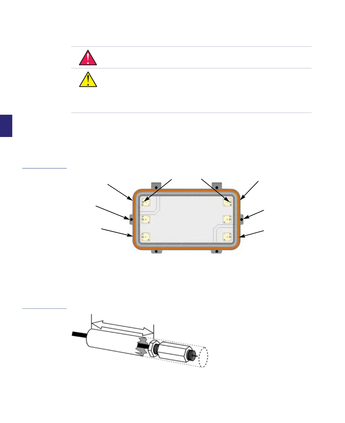
Figure 4.8
Centerseizure
Assemblies (with RF
module removed)
2. If using heatshrink tubing, prepare a heatshrink boot according to specifications supplied
by the manufacturer. Be sure that the boot is long enough to cover the cable entry port
insert and the entire connector. The boot must also extend at least 2 inches (5.08cm)
beyond the back nut. Slide the boot further onto the cable to allow access to the end of the
cable. Refer to Figure 4.9.
Figure 4.9
Heatshrink Boot
WARNING Hazardous voltages are present. Use approved safety procedures. Turn off
all power sources feeding into the unit before installing the cable and connectors.
CAUTION Centerseizure screws may not be captive. Modules manufactured after
June 1999 have either captive boots over these screws or captive screws that cannot
be backed out completely. Do not back non-captive screws out more than two full
turns since they can fall out into the housing and under the RF module, possibly
causing short circuits and definitely requiring removal of the RF module and service
interruption.
Centerseizure Screws
Port 4
Port 2
Port 5
Port 6
Port 1
Port 3
2
i
n
c
h
e
s
(
5
c
m
)