5
1502154 Rev D Configuration 5-3
Power Supply Configuration
Refer to Fuse Shorting Bar (Slug) Replacement on page 7-3 for all fuse removal and installation
procedures.
➤ To configure the power supply
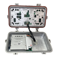
1. Open the amplifier housing. (Refer to Preparing for Installation on page 4-2 if necessary.)
2. Verify that an appropriate MAIN FUSE is installed. Table 5.2 lists the appropriate fuse
values for Flex Max901es. Inspect the fuse for obvious defects.
3. Check the system map to determine which ports receive or pass AC power. Verify that the
required fuses, brass shorting bars (slugs), or surge terminators are installed in the
appropriate port locations. Table 5.2 lists the maximum AC power passing approved for
these amplifiers.
4. If AC power is to be routed through two separate circuits—one for trunks and one for
bridger outputs—cut the AC distribution link (jumper wire). See Figure 5.1.
WARNING Hazardous voltages are present. Use approved safety equipment and
procedures.
CAUTION To prevent hybrid damage, C-COR recommends that all amplifiers in a
power supply group have PADs and Equalizers installed in the forward RF path before
energizing. The initial recommended accessory values are shown on the system map.
Table 5.2 Fusing/Power Passing Considerations
Power Supply Part
Number
Recommended
MAIN FUSE
Maximum Continuous
Current Passing
1
1. Refer to the system map for actual port fuse values.
Figure Reference
90V
AC, HEPS790
(2.3A)
122027-05 6.25A, slo-blo Ports 1, 3, 4, and 6: 15A
Ports 2 and 5: 13A
Figure 5.1