4
4-2 Flex Max901e 1GHz Trunk and Bridger Amplifiers 1502154 Rev D
Preparing for Installation
➤ To prepare for installation
1. Ensure that the following are included with each housing:
■ two (2) strand clamp assemblies (P/N HB0214), each consisting of:
– one strand clamp
– one 1/4-20 UNC x 1-inch bolt
– one lock washer
– one rubber O-ring (retaining)
■ metal port inserts (P/N MX0008) for each unused port
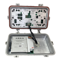
2. Inspect the outside of the housing (refer to Figure 4.1):
a. Check the convection fins, cable entry ports, lid bolts, and all testpoint connectors
for damage.
b. Ensure that each port is plugged with either a metal port insert or a plastic dust cap.
Materials
Heat gun or approved
torch and heatshrink
tubing, or weathersealing
tape or compound
— Weatherproofing RF cable connectors
1/4-20 UNC bolts and
shims
— Wall mounting
Metal port inserts C-COR P/N MX0008 Cover unused ports
Anti-seize compound — RF cable attachment
1. An 11mm tool can normally be used for a 7/16-inch bolt unless the tool is manufactured to minimum, and the
bolt head to maximum, “across the flat” dimensions.
2. Small, hold-down screws may be Phillips head screws or Torx PLUS
®
head screws. Use the appropriate driver.
3. C-COR recommends torquing all bolts and screws to the specified values.
Table 4.1 Tools and Materials (cont’d)
Tools/Equipment Required Specifications Uses
CAUTION Check the unit for damage. If there is shipping damage, contact the
shipping company and the C-COR Customer Service Department.