5
5-16 Flex Max901e 1GHz Trunk and Bridger Amplifiers 1502154 Rev D
Forward Balancing Requirements
Make sure that the following requirements are met before you start to balance:
■ The system map is marked with amplifier output levels for bandedge frequencies.
■ Forward balancing carriers, set at the proper levels, are injected into the cable network
from the headend.
■ One forward balancing carrier is available at a lower bandedge.
■ One forward balancing carrier is available at a higher bandedge.
■ RAW DC, B+, and B+ ripple voltages are within acceptable range (refer to Voltage Testing
on page 5-5 as necessary).
■ All tap outlets, ends of feeder cables, and unused active RF ports are terminated with a 75Ω
impedance.
■ Unscrambled ALC carriers are injected into the system at the assigned frequency for the
amplifier (if ALC is to be used).
■ The correct ALC PAD value is installed for NTSC or QAM channel ALC operation. The ALC
PAD ships with factory-installed NPB series PADs for standard NTSC operation. Refer to
the tables on page 5-15 for exact NPB PAD values.
■ Preceding amplifiers have been properly balanced and provide the desired forward band
signals to the amplifier for forward balancing.
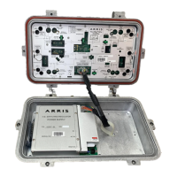
■ Flex Max901e trunk and bridgers amplifiers can be configured with the appropriate plug-in
accessories for 1GHz operation or for use as spares in 750/870MHz systems. Refer to Power
Supply Configuration beginning on page 5-3.
CAUTION RF input signal levels greater than +45 dBmV @ 1 NTSC channel loading
can damage amplifier active components. Derate maximum input level according to
actual channel loading (for example, +26 dBmV @ 79 NTSC channel loading)
(+26 dBmV = +86 dBµV).
Note “System” values are those recommended values shown on the system map.
“Measured” values are the signal levels actually measured at the amplifier.
Note While SEQ-1G and SCS-1G plug-in accessories will address all bandwidths up to
1GHz, you may wish to reuse your current equalizers and cable simulators until you
expand your system to 1GHz. Refer to the bulleted items in Step 3 under Upgrade
Considerations on page 3-2 to determine which plug-ins can be reused.