7
1502154 Rev D Maintenance 7-9
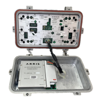
Power Supply Replacement
➤ To remove the power supply
1. Disconnect the power supply plug from the RF module POWER PLUG connector.
2. Use a #2 Phillips screwdriver to loosen, but not remove, the four power supply hold-down
screws.
3. Slide the power supply toward the RF module. Then lift it straight out of the housing.
➤ To install the power supply
1. Orient the replacement power supply with the four screw holes aligned over the
corresponding hold-down screws in the housing lid. Refer to Figure 2.1 on page 2-2. Lower
it onto the screws and slide it away from the RF module.
2. Use a #2 Phillips screwdriver to tighten the power supply hold-down screws. Torque to
between 17 and 20 in-lbs (2.0 and 2.3N·m).
3. Configure the power supply according to Power Supply Configuration on page 5-3.
4. Connect the power supply plug to the RF module POWER PLUG connector.
WARNING Hazardous voltages are present. Use approved safety equipment and
procedures.