6
6-6 Flex Max901e 1GHz Trunk and Bridger Amplifiers 1502154 Rev D
4. Calculate the true return amplifier gain by subtracting the input signal level (set in Step 2)
from the output level measured at the PORT 1 REV O/P TP. The difference should equal
the operational gain of the amplifier (at the balancing carrier) minus insertion losses from
accessories installed in the return path. Refer to When the Equalization Value is Known on
page D-1 to determine insertion losses at the high carrier frequency. Replace the RF module
if the amplifier gain measured at any port is out of tolerance.
5. Repeat this procedure for all active return ports.
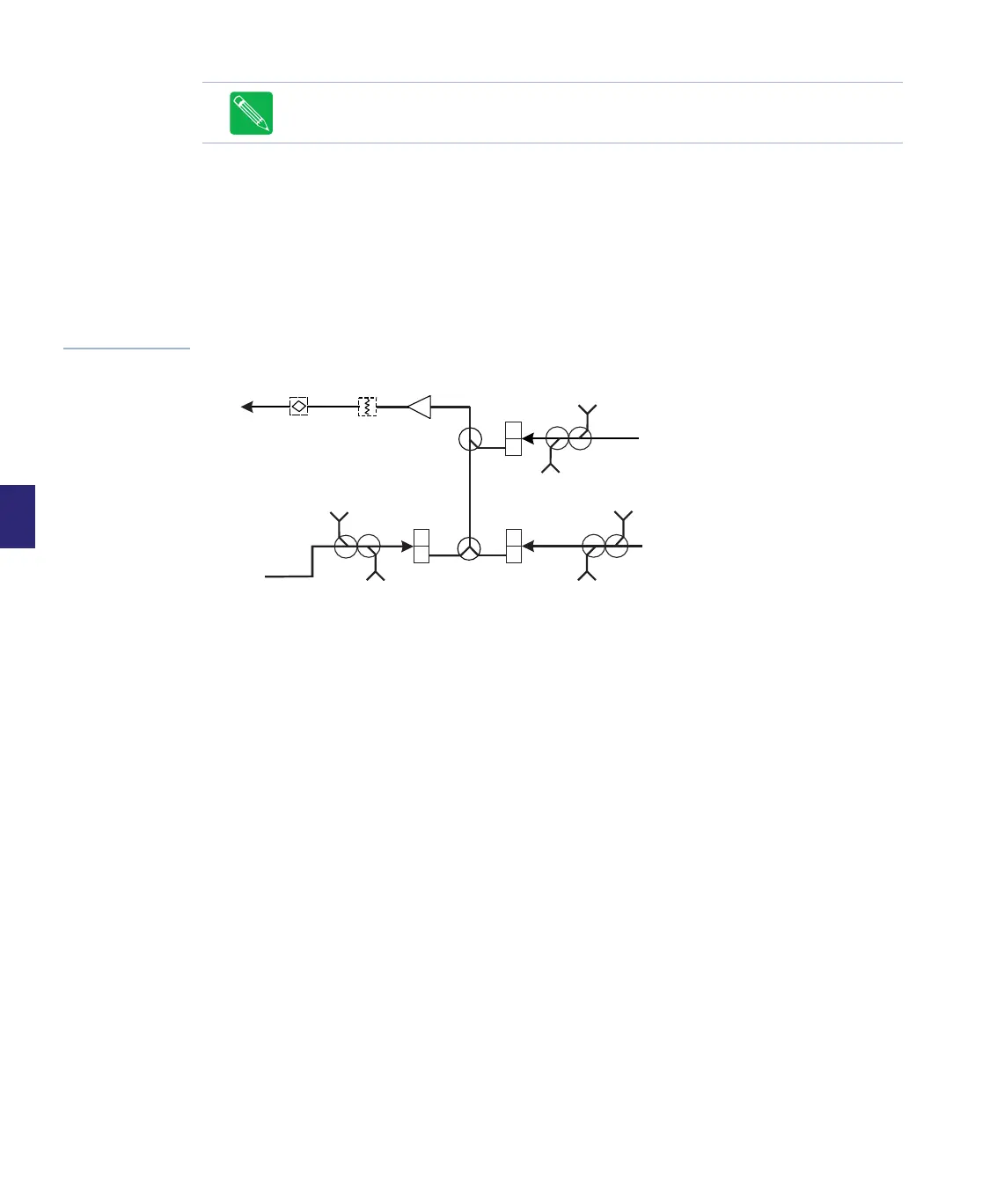
Figure 6.2
Simplified Return
Path Block Diagram
Note The Operational Gain listed on a C-COR Amplifier Specification Sheet is the gain
at the high bandedge frequency and includes 1.0 dB of loss for the return equalizer.
H
L
H
L
H
L
Port 4
Ports
2 and 3
Ports
5 and 6
Port 1
REV
EQ
STATION
REV PAD
PORT 4
REV I/P
TP
PORT 4
FWD O/P
TP
PORT 2/3
REV
I/P TP
PORT 2/3
FWD
O/P TP
PORT 5/6
REV I/P
TP
PORT 5/6
FWD O/P
TP