EasyManua.ls Logo

Calrec Apollo - VCA GROUPS

Calrec Apollo
124 pages
Print Icon
To Next Page IconTo Next Page
To Previous Page IconTo Previous Page
Loading...
104 APOLLO Digital Broadcast Production Console Panel Options
SWITCH 14 - BOOT STATUS
Input 2
Input 114/1
14/2
Switch
Boot-up status
14/3
14/4
Input 3
Input 4
SWITCH 10/1 - LOW FREQ FILTER
SWITCH 10/2 - HIGH FREQ FILTER
LF filter bypassed
LF filter active0
1
Sw 10/1
LF filter status
HF filter bypassed
HF filter active0
1
Sw 10/2
HF filter status
1 2 3 41 2
ON ON ON ONONON
1 2
ONON
1 2
ONON
1 2
ONON
1 2
ONON
1 2
ONON
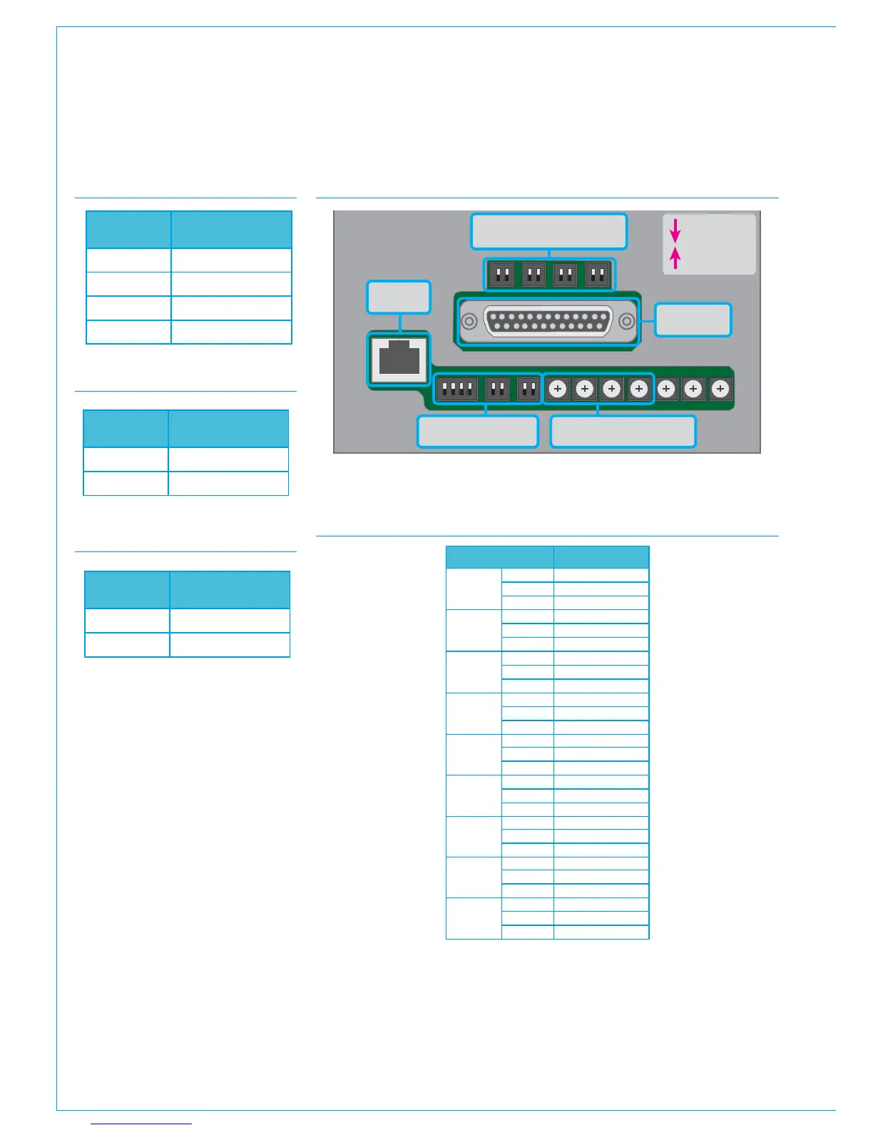
RJ45 POE
power in
SW1SW2SW3SW4
= ON / “1”
= OFF / “0”
SW14 SW10 SW9
Input Enables
Options
SW8 SW7 SW6 SW5
Color Select
D25 - Audio
inputs
REAR OF PANEL - CONNECTOR AND DIP SWITCH LOCATIONS
D25 - REAR OF PANEL AND REAR INTERFACE LS CONNECTOR PIN-OUT
Analog input Pin
1 Left
+ 1
- 14
Ground 3
1 Right
+ 2
- 15
Ground 3
2 Left
+ 16
- 4
Ground 18
2 Right
+ 17
- 5
Ground 4
3 Left
+ 6
- 19
Ground 8
3 Right
+ 7
- 20
Ground 8
4 Left
+ 21
- 9
Ground 23
4 Right
+ 22
- 10
Ground 23
Logic
Ext Cut 11
Ext Dim 24
Ground 13

Table of Contents

Other manuals for Calrec Apollo

Related product manuals