110 APOLLO Digital Broadcast Production Console Moving Coil Meters
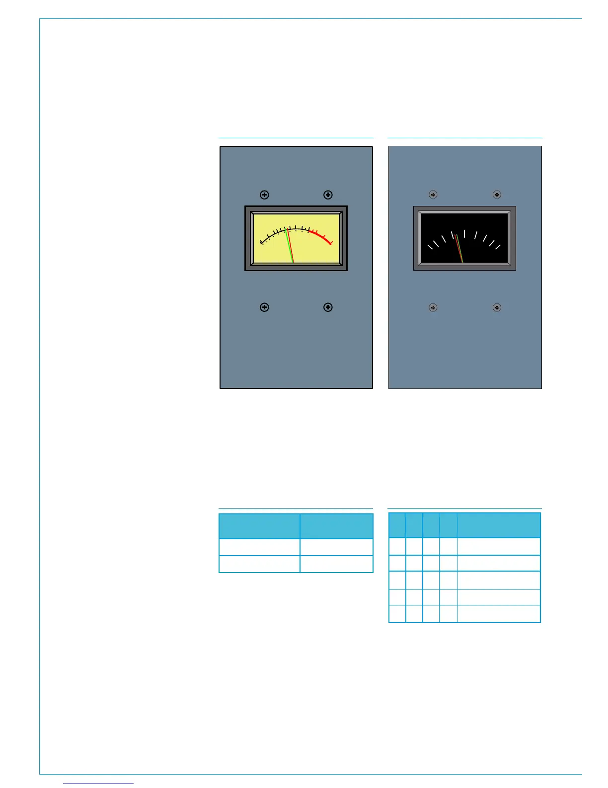
STEREO MOVING COIL METERS
+1
VU
+3
+2
0
-2
-1
100
80
-3
-7
-5
60
40
-10
0
20
-20
VU
R/GR/G
The MV5778 has VU scaling and
ballistics, the MU5775 has PPM
scaling and ballistics. Both are dual
needle, stereo moving coil meters.
These panels are 130mm [5.12'] wide, and
as such are often fitted above the monitor
or joysticks panels which are the same
width.
Moving coil meters do not access the
meter data system and require an audio
feed via the console's rear connector
interface. If the meter is to be fed directly
from console outputs, this should be
provisioned for in the quantity of Hydra2
output ports ordered.
Moving coil meters can be fed with either
digital or analogue audio signals. The
inputs are mixed rather than switched
however so only one format should be fed
at any given time.
Connections
Audio is received via a female D25
connector on the console's rear interface
panel. This wires internally to a female
D9 on the back of the meter panel itself.
See the Surface Rear Connector Pin-outs
section for wiring detail.
The meter panels are powered via a single
RJ45 connection fed from a POE switch
ancillary power port.
DIP switch configuration
PCB mounted DIP switches provide
some configuration options for moving
coil meters. To access these switches,
the panel needs to be removed from the
control surface. Once removed, the drive
card for the meters is accessible from the
rear.
Level
A bank of 4 switches is used on each
audio leg to set the level to be displayed
on the meters at line-up.
1
2
3
4
5
6
7
MV5778 - STEREO VU METER MU5775 - STEREO PPM METER
These are adjusted to compensate for the
meter type fitted and operating level. The
table below shows which bank of switches
is used for each audio channel.
Each bank of four switches should be set
as per the table below for the required
line-up level.
Audio Path
Left
Right
Switch
SW 3
SW 2
1 2 3 4
Level
0 0 0 0
1000
1001
1011
1111
0
-2
-4
-6
-15
LEVEL SWITCH SETTINGSCHANNEL LEVEL SWITCHES