44 APOLLO Digital Broadcast Production Console Connection Information
SURFACE TO CORE CONNECTION
A connection is required between the
Control processors in the processing
core and the Surface Switches inside
the control surface.
These connections are via SFPs, the
SFP type will be either fibre or copper,
as requested at order depending on the
distances and infrastructure involved.
Calrec do not provide these
interconnecting fibres / cables as
the length, type and quality will vary
depending on the specific requirements of
each installation.
Copper connections should be made
using screened Cat5e or Cat6 cable. For
more information on copper connections,
SFPs and fibres, please see the
Connection Types and Cat5e Cables
sections.
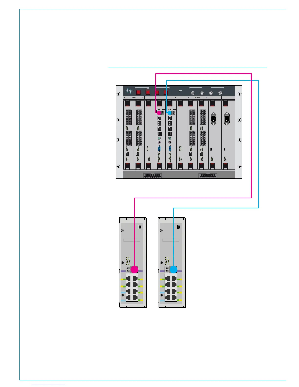
The illustration to the right shows the
location of the connections on the core
and surface switches.
The two surface switches are located
inside the control surface, mounted to
the rear cover of the section containing
the IEC mains power inlets. These can be
accessed by removing the control surface
panels and upstand meter panels in that
area of the console.
The two surface switches should be easily
identifiable on the rear cover. The left
hand unit, when viewed from the front is
the primary Surface Switch, the right hand
unit is the secondary Surface Switch.
In the processing core, the card labelled
'Control Processor 1', in slot 4 is the
Primary Control processor, whilst slot 5
'Control Processor 2' is the secondary
Control processor.
CONTROL
ROUTER / EXPANDER
ENABLEDSPSYSTEM
RESETS
FAIL
GOOD
FANS
AES 3 VIDEO 2
VIDEO 1
WORD
CLOCK
SYNC INPUTS
DSP 1 PROCESSOR 1 PROCESSOR 2 DSP 2 PSU 1 PSU 2
CONTROL
EXPANSION 1 ROUTER 1 EXPANSION 2ROUTER 2
POK ST0
ST1 ST2
ST3 ST4
ST5 ST6
AC IN
USB
ST1 ST2
ST3 ST4
ST5 ST6
AC IN
USB
POK ST0
ROUTER / EXPANDER PSU PSUROUTER / EXPANDER ROUTER / EXPANDER
DSPDSP
ROUTER / EXPANDER
POK MA
PRI RST
MOK NOK
ST1 ST2
POK MA
PRI RST
MOK NOK
ST1 ST2
POK MA
PRI RST
MOK NOK
ST1 ST2
POK MA
PRI RST
MOK NOK
ST1 ST2
POK MA
PRI RST
MOK NOK
ST1 ST2
POK MA
PRI RST
MOK NOK
ST1 ST2
D1D2
D3
D4
D5
D6
D7
D8
D1D2
D3
D4
D5
D6
D7
D8
9
11
13
15
10
12
14
16
1
3
5
7
2
4
6
8
10 9
12 11
14
13
16 15
2 1
4
3
6
5
8
7
ETHERNET
LINKS
LINKS
9
11
13
15
10
12
14
16
1
3
5
7
2
4
6
8
10 9
12 11
14
13
16 15
2 1
4
3
6
5
8
7
ETHERNET
LINKS
LINKS
9
11
13
15
10
12
14
16
1
3
5
7
2
4
6
8
10 9
12 11
14
13
16 15
2 1
4
3
6
5
8
7
ETHERNET
LINKS
LINKS
9
11
13
15
10
12
14
16
1
3
5
7
2
4
6
8
10 9
12 11
14
13
16 15
2 1
4
3
6
5
8
7
ETHERNET
LINKS
LINKS
CONTROL PROCESSOR
MAC 6
MAC
4
MAC
3
MAC
5
USB
1
MOUSE
KBD
VGA
D1D0
R1R0
E1E0
MAPOK
RSTPRI
NOKMOK
ST2ST1
LOW BATTCF
USB
2
MAC 7
CONTROL PROCESSOR
MAC 6
MAC
4
MAC
3
MAC
5
USB
1
MOUSE
KBD
VGA
D1D0
R1R0
E1E0
MAPOK
RSTPRI
NOKMOK
ST2ST1
LOW BATTCF
USB
2
MAC 7
USB
YZ5716-2
Surface Switch
IP
PS
PR
PS1
PS2
PS3
PS4
PS5
PS6
PR1
PR2
- Input Power
- POE Switch
- Power & Reset
IP2
2
4
6
1
3
5
IP1
AB
Serial number
USB
YZ5716-2
Surface Switch
IP
PS
PR
PS1
PS2
PS3
PS4
PS5
PS6
PR1
PR2
- Input Power
- POE Switch
- Power & Reset
IP2
2
4
6
1
3
5
IP1
AB
Serial number
Primary Secondary
CORE TO CONSOLE CONNECTIONS
A connection should be fitted
between the Primary Surface Switch
port 'A' and the Primary Control
processor's 'MAC7' port.
A backup connection should be fitted
between the Secondary Surface
Switch port 'A' and the Secondary
Control processor's 'MAC7' port
It is important to ensure that these
connections are made correctly - primary
to primary and secondary to secondary, as
well as using the correct ports.