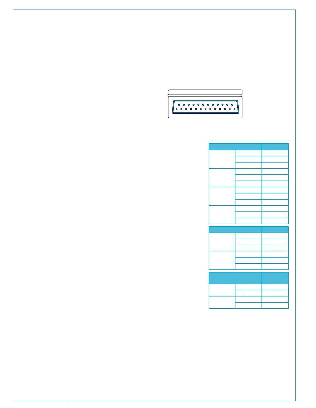
MOVING COIL METER INPUTS
All audio is processed within the
core, the system does not pass audio
to or from the control surface on its
own. Calrec TFT and LED metering
in the control surface functions on
proprietary meter data which is not
decoded for listening and cannot
be used by 3rd party or ancillary
hardware.
Ancillary audio items such as moving coil
meters, 3rd party meters such as DK or
RTW, headphones, talkback mics, optional
loudspeaker panels etc all require an
audio connection to the rear interface
panel of the control surface if they are to
be used.
If these items are to be fed directly from
console I/O, they should be provisioned
for in the quantity of Hydra2 I/O ordered.
Loudspeaker and some moving coil meter
panels are fitted with DIP switches that
can disable inputs and set levels. Please
refer to the Panel Options section of this
document for more detail on each panel
type.
• If feeding unbalanced AES digital,
BOTH signal pins and BOTH
ground pins shown for each leg
need to be connected.
• Input 2 not used for twin single
needle VU meter, or single dual
needle meter panels.
• One D25 connector per single /
dual or quad meter panel (multiple
panels are not combined onto a
single rear connector).
• 6 way VU panels require a second
D25 connection for meters 5 & 6,
pinned out as per the Left1/ Right1
/ AES1 inputs shown.
• Analogue and digital inputs
are both active, not switched.
Therefore only one format should
be fed to the meter at any given
time.
• Refer to Panel Options section for
DIP switch setup information about
moving coil meters.
All D-type audio connectors on the
interface panel are all 25 pin female,
requiring male terminated cabling.
Analogue Inputs Pins
Left 1
+ 1
- 14
Ground 2
Right 1
+ 15
- 3
Ground 4
Left 2
+ 7
- 20
Ground 22
Right 2
+ 21
- 9
Ground 23
Balanced Digital Inputs Pins
AES 1
+ 18
- 6
Ground 5
AES 2
+ 24
- 12
Ground 25
Unbalanced Digital
Inputs
Pins
AES 1
Signal 4 + 18
Ground 5 + 6
AES 2
Signal 10 + 24
Ground 11 + 12
Moving coil meters
Important notes on moving coil meter
wiring: