Power Supply
Card slots 9 & 10 are for PSU modules.
Both slots share the power load for the
whole core. One PSU module is sufficient
to power the whole core, two are fitted to
provide redundancy.
Each card has an IEC AC mains input
connector, requiring 100-240V AC.
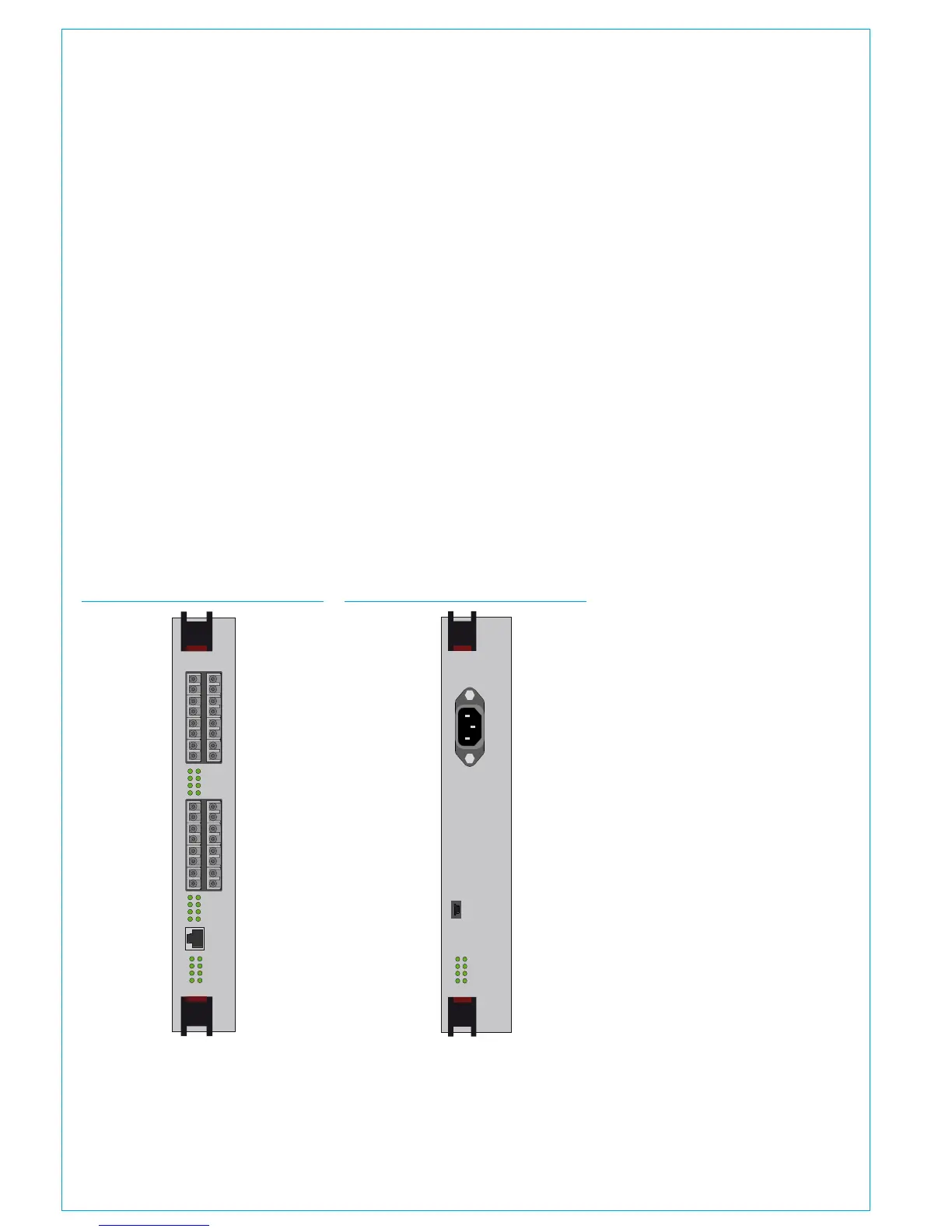
Router / Expander
The primary, normally active router card
fits in slot 2, the secondary in slot 7. As
an option, slots 1 and 8 can be fitted with
additional router modules of the same
type to double the number Hydra2 I/O
ports in the core.
The Apollo router card has 16 SFP ports
that can be fitted with copper or fibre
SFP's to allow connection of Hydra2 I/O
boxes and connections to other consoles'
r o u t e r s a n d s t a n d a l o n e r o u t e r c o r e s .
A single RJ45 port labelled Ethernet
allows for the connection of 3rd party
equipment supporting the SW-P-08 or
Ember protocols for remote control.
As well as standard status LED's there are
front panel LED indicators to show activity
on each port.
FIGURE 4 - ROUTER / EXPANDER
ROUTER / EXPANDER
POK MA
PRI RST
MOK NOK
ST1 ST2
9
11
13
15
10
12
14
16
1
3
5
7
2
4
6
8
10 9
12 11
14
13
16 15
2 1
4
3
6
5
8
7
ETHERNET
LINKS
LINKS
FIGURE 5 - PSU MODULE