58 APOLLO Digital Broadcast Production Console
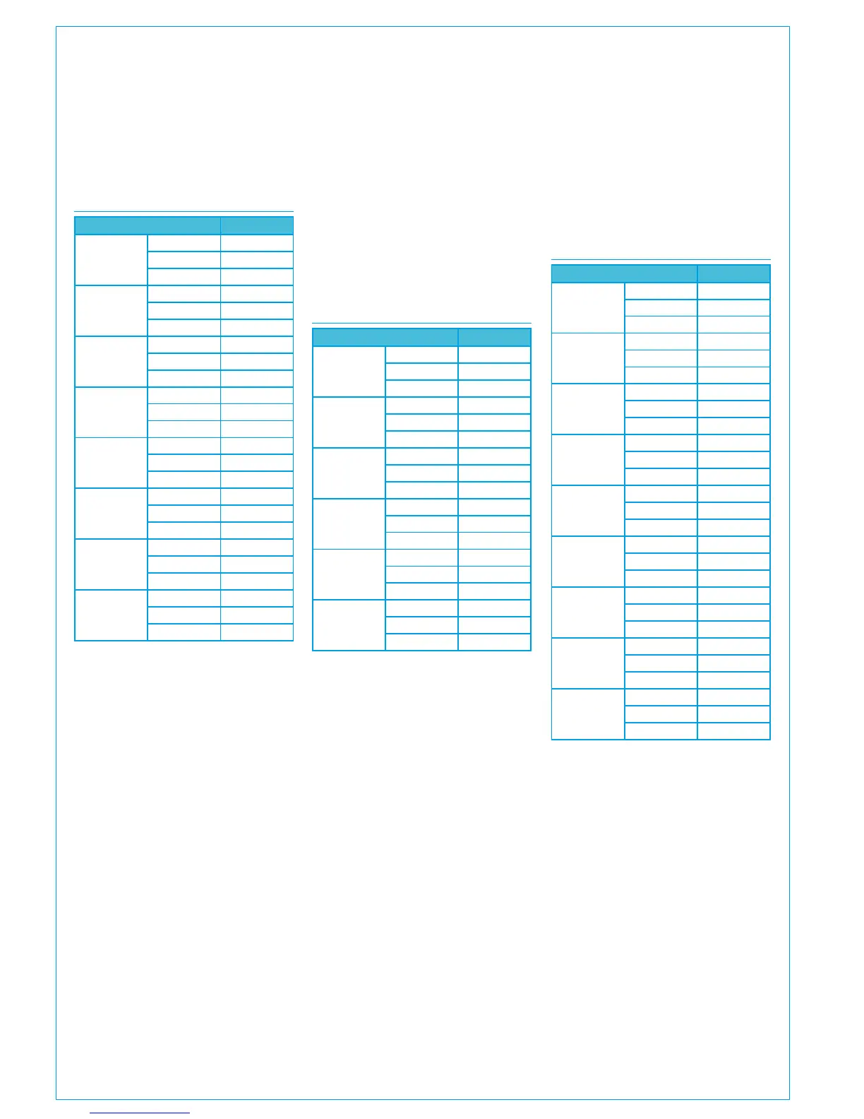
Connection Information
HEADPHONE INPUTS
Input Pins
1 Left
+ 1
- 14
Ground 2
1 Right
+ 15
- 3
Ground 16
2 Left
+ 18
- 6
Ground 19
2 Right
+ 7
- 20
Ground 8
3 Left
+ 21
- 9
Ground 22
3 Right
+ 24
- 12
Ground 25
• Refer to the panel options section
for LS panel DIP switch input
enabling information.
BALANCED ANALOGUE ONLY DK
INPUTS
Input Pins
1
+ 1
- 14
Ground 2
2
+ 15
- 3
Ground 16
3
+ 4
- 17
Ground 5
4
+ 18
- 6
Ground 19
5
+ 7
- 20
Ground 8
6
+ 21
- 9
Ground 22
7
+ 10
- 23
Ground 11
8
+ 24
- 12
Ground 25
• Quantity of inputs available
dependent on the number of input
cards ordered.
• Each analogue only input card has
a female D25 connector on the
console rear interface, pinned out
as above.
Headphone sockets
The headphone driver unit in the control
surface has capacity for 3 stereo
balanced analogue inputs. The actual
quantity in use is dependent on the
number of headphone jack sockets fitted
/ requested at order.
Loudspeaker panels
Each loudspeaker panel fitted has 4
stereo balanced analogue inputs.
LOUD SPEAKER INPUTS
Input Pins
1 Left
+ 1
- 14
Ground 3
1 Right
+ 2
- 15
Ground 3
2 Left
+ 16
- 4
Ground 18
2 Right
+ 17
- 5
Ground 18
3 Left
+ 6
- 19
Ground 8
3 Right
+ 7
- 20
Ground 8
4 Left
+ 21
- 9
Ground 23
4 Right
+ 22
- 10
Ground 23
Logic
Ext Cut 11
Ext Dim 24
Ground 13