CALREC Putting Sound in the Picture 25
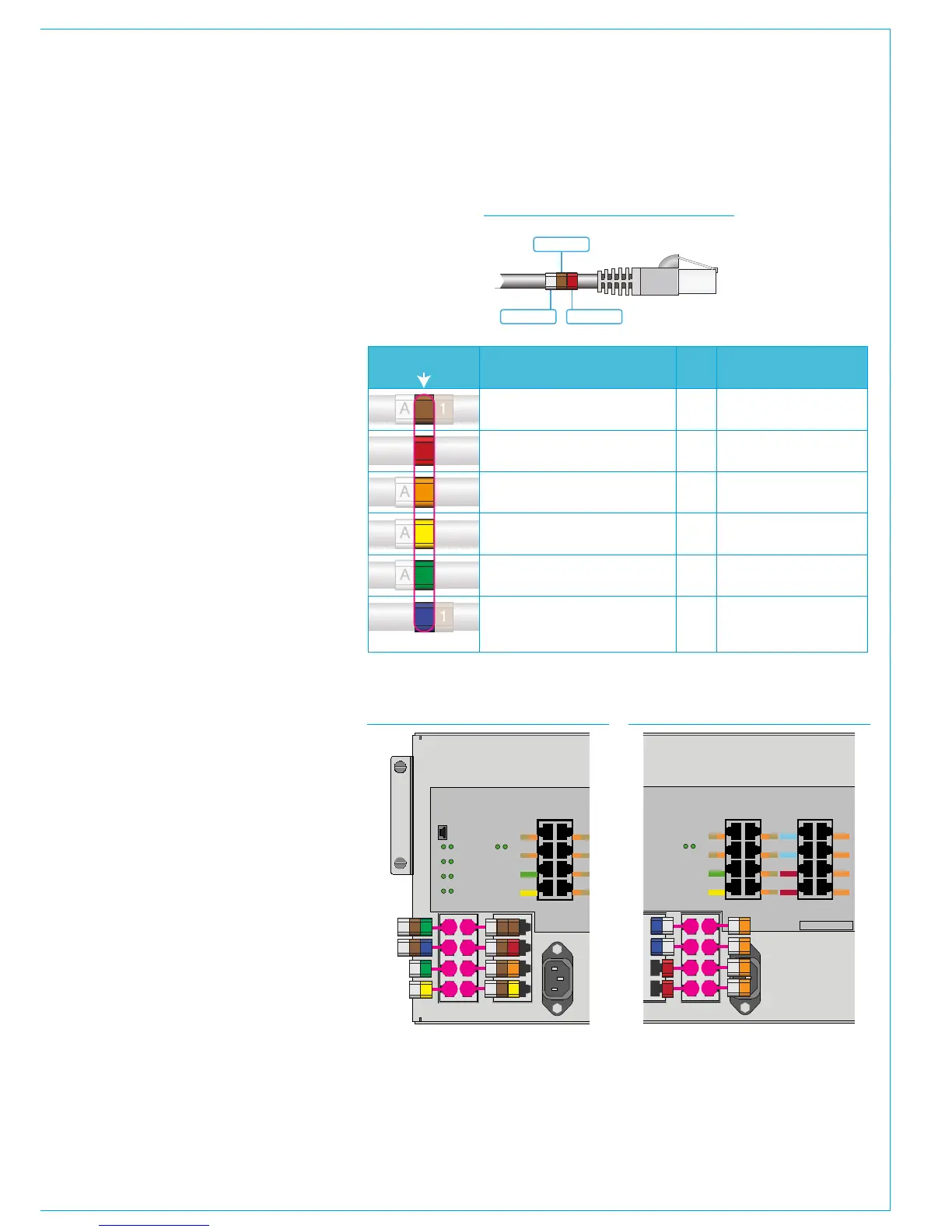
Cat5e network cabling inside the
control surface is ID coded at both
ends with a number of cable markers.
One marker is used on each to ID the
function of the cable by colour, matching
the colour key used for the connector
labelling on the POE switch - for example
the data connection to the primary surface
switch has a green marker and the one to
the secondary has a yellow one.
Depending on the function of the cable,
some have a prefix and/or suffix to the
function marker.
Prefixes are used to identify the control
surface section the related POE is fitted
in. Viewing the console from left to right,
the first frame section is 'A', second is
'B', third is 'C' etc. Where there is more
than one POE switch fitted in a section,
two letters are used to prefix the label,
for example 'AA' & 'AB' where AA is the
first POE in the first section and AB is the
second POE in the first section.
Panel connection cables use a suffix to
ID the POE port. For example, if a cable
is labelled 'A11' - The prefix 'A' refers to
the POE switch in section 1. The next
character '1' is a colour marker (brown) to
identify the cable as a panel connection,
and the last character, or suffix - '1' refers
to port P1.
Blue SPR connections use a suffix to
identify the device being powered by the
POE switch.
The table to the right lists the functions
with prefix and suffix by colour ID. Figures
2 & 3 give examples of the cable labels
that would be used for the first POE's A &
B group of ports.
A 1
A
A
A
1
1
2
3
4
5
6
Colour ID
Control panel connection, data & power
Prefix Suffix
Reset connection (RST)
Ancillary power (AP1-4)
Secondary Surface Switch (S2), data
Primary Surface Switch (S1), data
Uninterrupted power + reset (SPR1-2)
Section
ID
1-6, relates to
POE P1-P6 port ID
Section
ID
Section
ID
Section
ID
None
None
None
None
None
None
1 = Primary Surface Switch
2 = Secondary Surface Switch
3 = PC Power 1
4 = PC Power 2
Function